EKC 531D1 Instructions RI8HU352 © Danfoss 12/2004 3
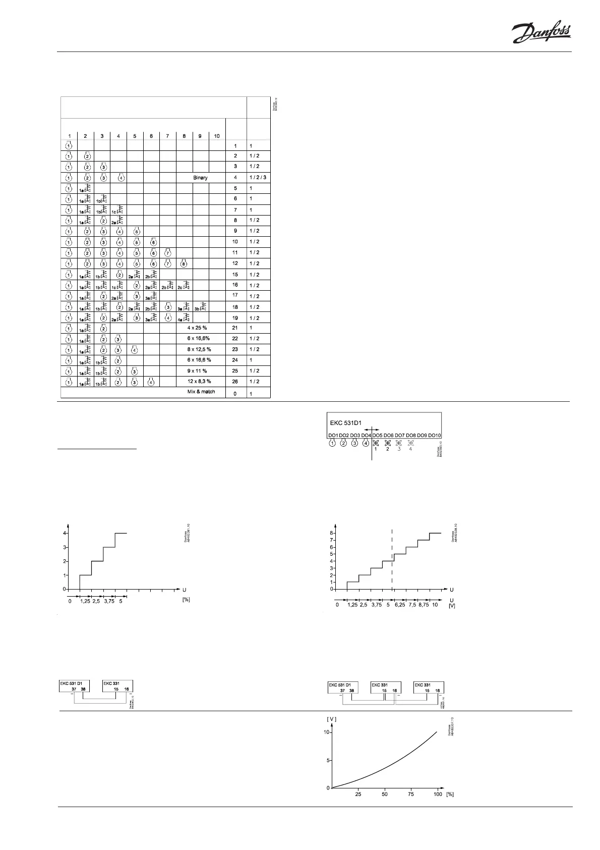
Compressor connections
Coupling
mode
Relay no.
Set
"C08"
to
Set
"C16"
to
User-defi ned combination.
Capacity step
All capacity steps are presumed to
be identical. The only exception is
the settings C16 = 0, 4, and 21 to 26.
Coupling mode
Coupling mode 1 = sequential
operation.
Coupling mode 2 = cyclic operation.
Coupling mode 3 = cyclic and binary
operation where the compressor
capacities are, as follows:
1: 9%
2: 18%
3: 36%
4: 36%
There is cyclic coupling at 3 and 4,
and binary on 1, 2 and 3/4.
(for c16=4 only)
Compressor confi guration
Setting "C16" will defi ne the confi guration.
Setting "C08" will defi ne coupling mode.
Couplings
When there is cyclic operation and
connections with unloaders there
will in some capacity cutins and
cutouts be overlappings where
the unloaders from either one
compressor or another may be
active.
In such cases the unloaders on the
compressor with the lowest number
of hours will be cut in, and the others
cut out.
The changeover will take place at
6-second intervals.
Equalised operation
When C16 = 21 to 26, compressor
1 + belonging unloader must have
the same capacity as each of the
subsequent compressors. The
unloading function will equalise the
cut-in capacity when the subsequent
compressors are cut in and out.
Compressor 1 will always be
operating.
Output signal from EKC 531D1
In EKC 331 the voltage range must be set to 0-5 V (“o10” = 6).
In EKC 331 the number of steps must be set to 4 (“o19” = 4) (also when
fewer fans are connected).
Output signal from EKC 531D1
In the fi rst EKC 331, set 0-5 V (“o10” = 6).
In the second EKC 331, set 5-10 V (“o10” = 7).
In both EKC’s the number of steps must be set to 4 (“o19” = 4) (also when
fewer fans are connected to the second EKC).
If the entire condenser capacity is to be controlled by a
frequency converter, EKC 531D1 must send an analog
signal about the required capacity (“c29” = 9).
The signal varies from 0 to 10 V. Signal and capacity
have the following context.
Condenser couplings
When the compressor relays have been established the turn
comes to the fan relays.
The fi rst vacant relay (DO1-DO8) will become the fi rst fan relay.
It will be followed by the subsequent relays. If more relays are
required than the vacant DO relays, a relay module can be
connected to the analog output. The function is, as follows:
If there are up to four external fans on an EKC 331:
1. 2.
If there are more than four external fans on two EKC 331 units:
Connection
Connection
 Loading...