MCD500 PCB Replacement MCD 500 PCB Replacement - Instructions
MI.17.F1.02 - VLT
®
is a registered Danfoss trademark Page 3/5
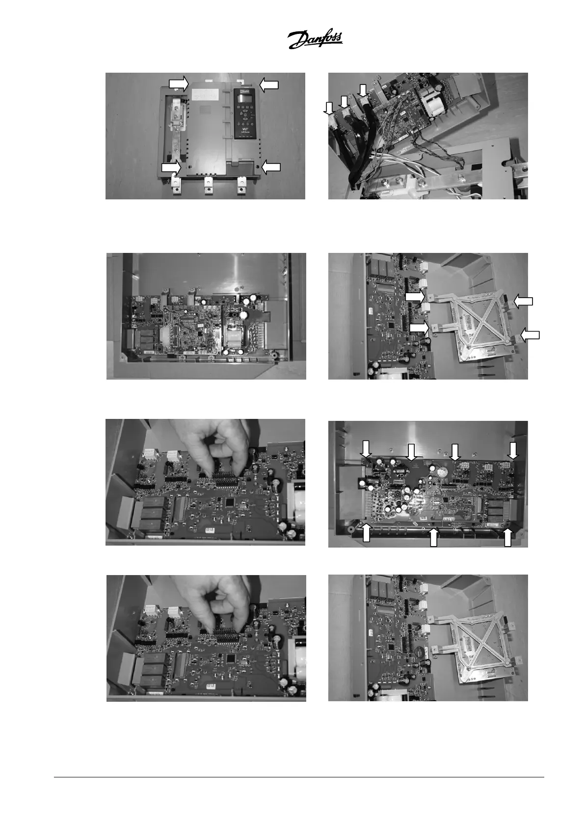
3. Model MCD5-0245C
Remove the top cover and terminal blocks from
the starter. Undo the 4 x Torx screws holding the
top plastic.
Tilt the top plastic to the right to expose the wiring
looms. Label each SCR firing loom with the number
of the corresponding phase terminal on the main
control PCB, then unplug the SCR firing looms
Unplug the thermistor, fan and CT wires from the
LCP and main control PCB and set the top plastic
aside.
Undo the 4 x Torx screws from the model PCB
support bracket and set aside.
Unplug the header connector from the main
control board and set aside.
Remove 7 x Torx screws. Replace the LCP and main
control PCB assembly. Replace the 7 x Torx screws
Replace the header connector.
Replace the model board, check that the header
connector pins line up with the main control PCB
below.
 Loading...