MCD500 PCB Replacement MCD 500 PCB Replacement - Instructions
MI.17.F1.02 - VLT
®
is a registered Danfoss trademark Page 5/5
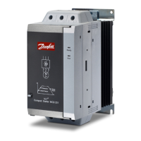
Unplug the header connector from the main
control PCB and set aside.
Remove 7 x Torx screws. Replace the LCP and main
control PCB assembly. Replace the 7 x Torx screws.
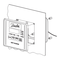
Replace the header connector.
Replace the model board, check that the header
connector pins line up with the main control PCB
below.
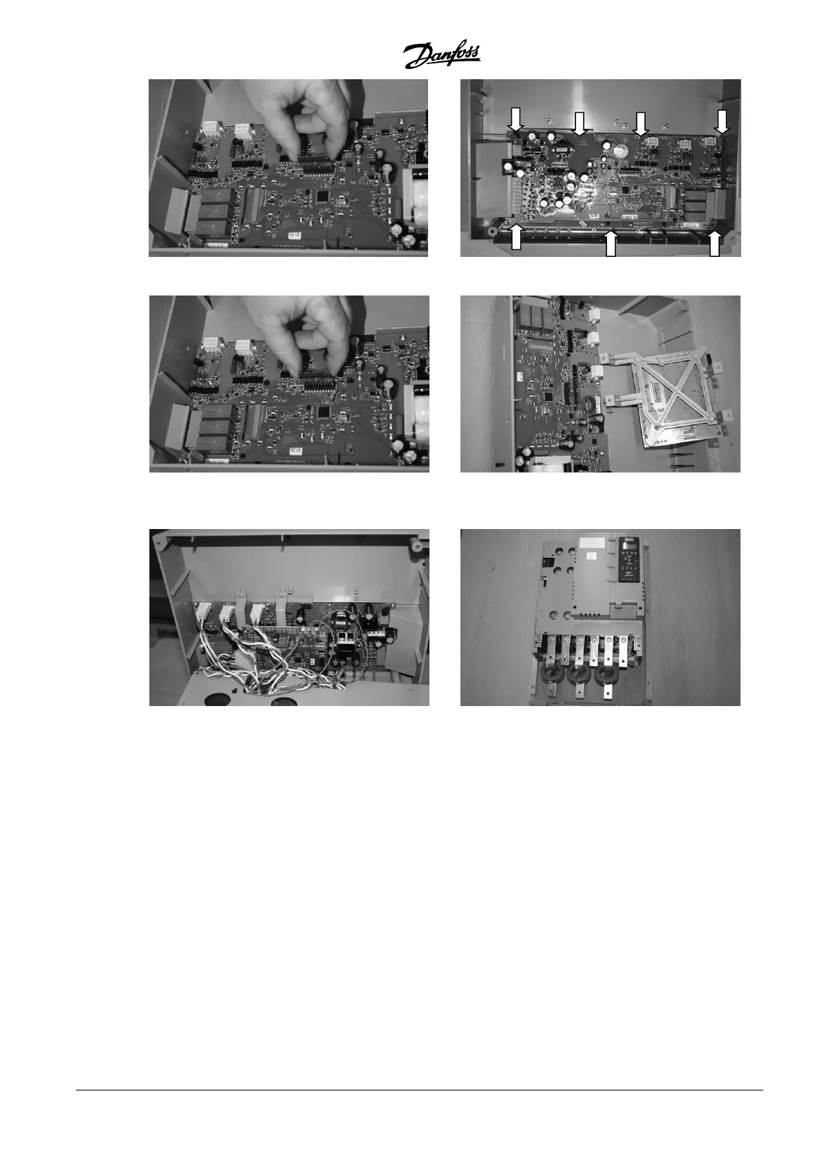
Replace the PCBs, plug in the looms, and replace
the LCP, top cover and terminal plugs. Take note
of the thermistor wiring (grey/red) to the right,
and fan wiring (black/red) to the left of the board.
Replace the 4 x Torx screws to secure the top
plastic and replace the top cover and terminal plugs.
 Loading...