5
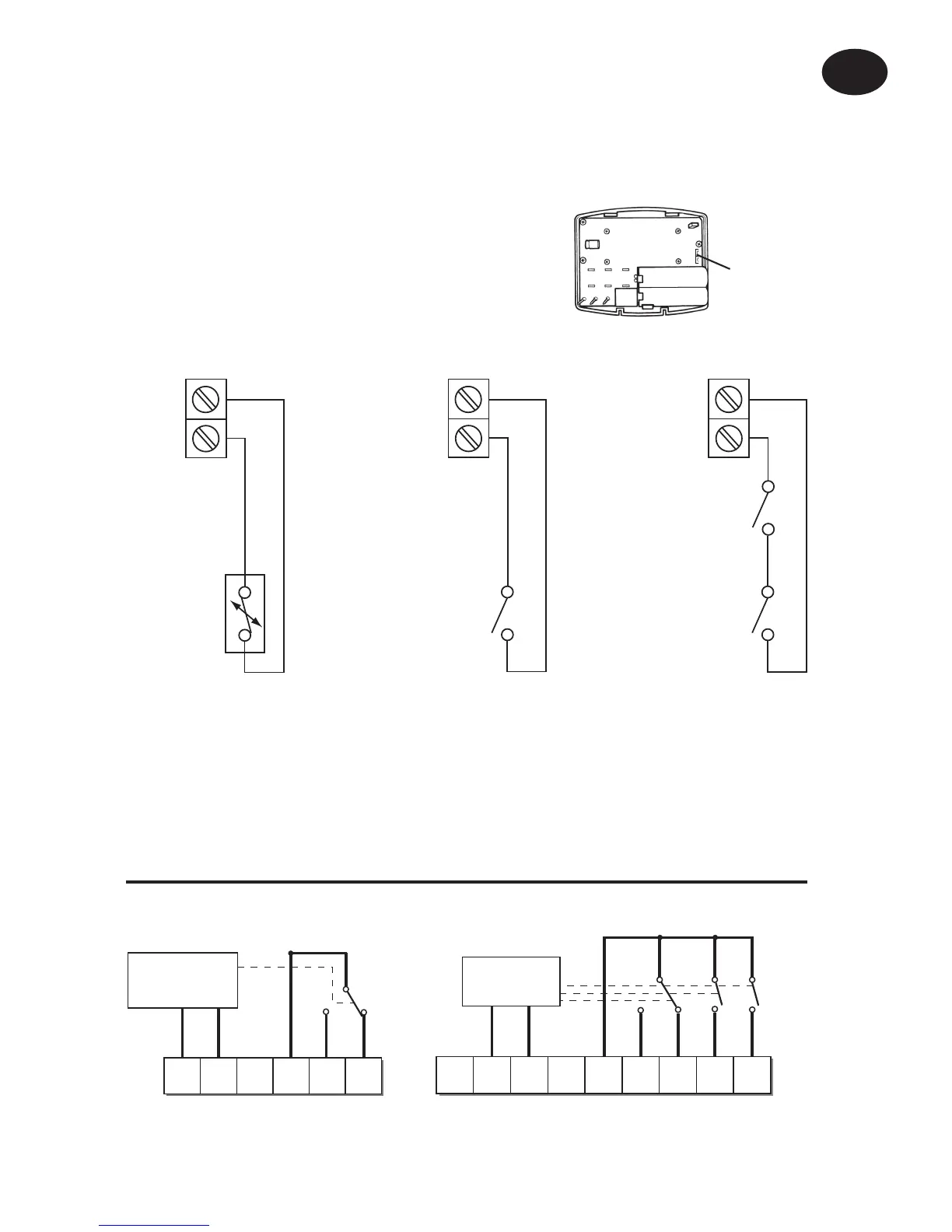
Models with remote sensor inputs
Terminal block for remote control/sensing
is located on the circuit board above the
battery compartment.
RX1
RX2 & RX3
12
3
4
ELECTRONICS
N
L
COM
ZONE
1 ON
ZONE
1 OFF
A
ELECTRONICS
B
C1
2
345
6
N
L
ZONE
1 ON
ZONE
1 OFF
ZONE
2 ON
ZONE
3 ON
COM
TERMINAL 6
RX3 ONLY
RX Receiver Wiring (RF models only)
1) For mains voltage operated systems link terminal 2 to mains live supply.
2) Power supply to unit must not be switched by timeswitch.
Installation Instructions
GB
S1/D
S2/E
S1/D
S2/E
Window or
teleswitch
contact
(NO or NC)
Teleswitch
contact (NC)
Window
contact (NC)
S1/D
S2/E
Confi gured for
remote room
sensor or limit
sensor
Confi gured for
window contact or
other contact such
as teleswitch
Confi gured for
window contact
and other contact
such as teleswitch
E
Remote
control
connections
2) limit sensor, for example, fl oor temperature sensor (sold as
accessory).
3) window contacts, card reader contacts or teleswitch contacts.
See Installer Advanced Programming Options for set-up instructions.
 Loading...