Mains Supply Interference/Harmonics
A frequency converter takes up a non-sinusoidal cur-
rent from mains, which increases the input current
I
RMS
. A non-sinusoidal current can be transformed by
means of a Fourier analysis and split up into sine wave
currents with different frequencies, i.e. different har-
monic currents I
N
with 50 Hz as the basic frequency:
Harmonic currents
I
1
I
5
I
7
Hz 50 Hz 250 Hz 350 Hz
The harmonics do not affect the power consumption
directly, but increase the heat losses in the installation
(transformer, cables). Consequently, in plants with a
rather high percentage of rectifier load, it is important
to maintain harmonic currents at a low level to avoid
overload of the transformer and high temperature in
the cables.
Some of the harmonic currents might disturb commu-
nication equipment connected to the same transform-
er or cause resonance in connection with power-factor
correction batteries.
Harmonic currents compared to the RMS input cur-
rent:
Input current
I
RMS
1.0
I
1
0.9
I
5
0.4
I
7
0.2
I
11-49
< 0.1
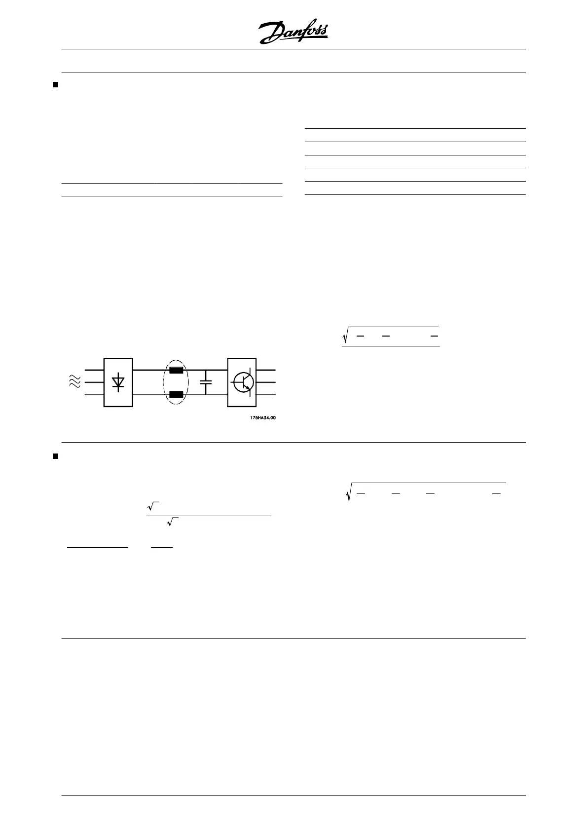
To ensure low, harmonic currents, the frequency con-
verter has intermediate circuit coils as standard. This
normally reduces the input current I
RMS
by 40%.
The voltage distortion on the mains supply depends on
the size of the harmonic currents multiplied by the
mains impedance for the frequency in question. The
total voltage distortion THD is calculated on the basis
of the individual voltage harmonics using the following
formula:
THD
%=
U
2
5
+
U
2
7
+ ..... +
U
2
η
U
1
(
U
η
%
of U
)
See also Application Note MN.90.FX.02.
Power Factor
The power factor is the relation between I
1
and I
RMS
.
The power factor for 3-phase control:
Power factor
=
3×
U
×
I
1
×
cos
ϕ
1
3×
U
×
I
RMS
I
1
×
cos
ϕ
1
I
RMS
=
I
1
I
RMS
since cos
ϕ =1
The power factor indicates the extent to which the fre-
quency converter imposes a load on the mains supply.
The lower the power factor, the higher the I
RMS
for the
same kW performance.
In addition, a high power factor indicates that the dif-
ferent harmonic currents are low.
I
RMS
=
I
2
1
+
I
2
5
+
I
2
7
+ ..... +
I
2
n
VLT
®
5000 Design Guide
120 MG.52.B2.02 - VLT
®
is a registered Danfoss trademark
 Loading...