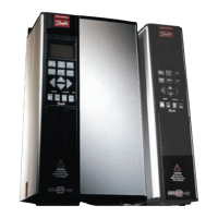
VLT
®
5000 Series
Technical
data
Control card, 24 V DC supply:
Terminal nos. ................................................................................................................................................ 12, 13
Max. load (short-circuit protection) ............................................................................................................. 200 mA
Terminal nos. ground .................................................................................................................................... 20, 39
Reliable galvanic isolation: The 24 V DC supply is galvanically isolated from the supply voltage
(PELV)*,buthasthesamepotentialastheanalogueoutputs.
* VLT 5001-5062, 525-600 V do not meet PELV.
Control card, RS 485 serial communication:
Terminal nos. .............................................................................................................. 68 (TX+, RX+), 69 (TX-, RX-)
Reliable galvanic isolation: Full galvanic isolation.
Relay outputs:
1)
No. of programmable relay outputs ...................................................................................................................... 2
Terminal nos., control card (resistive load only) ....................................................................................... 4-5 (make)
Max. terminal load (AC1) on 4-5, control card ........................................................................ 50 V AC, 1 A, 50 VA
Max. terminal load (DC1 (IEC 947)) on 4-5, control card ................................. 25 V DC, 2 A / 50 V DC, 1 A, 50 W
Max. terminal load (DC1) on 4-5, control card for UL/cUL applications .................... 30 V AC, 1 A / 42.5 V DC, 1A
Terminal nos., power card (resistive and inductive load) ...................................................... 1-3 (break), 1-2 (make)
Max. terminal load (AC1) on 1-3, 1-2, power card ............................................................. 250 V AC, 2 A, 500 VA
Max. terminal load (DC1 (IEC 947)) on 1-3, 1-2, power card ............................. 25 V DC, 2 A / 50 V DC, 1A, 50 W
Min. terminal load (AC/DC) on 1-3, 1-2, power card ....................................... 24 V DC, 10 mA / 24 V AC, 100 mA
1) Rated values for up to 300,000 operations.
At inductive loads the number of operations are reduced by 50%, alternatively the current can be reduced by
50%, thus the 300,000 operations are maintained.
Brake resistor terminals (only SB, EB, DE and PB units):
Terminal nos. ................................................................................................................................................ 81, 82
External 24 Volt DC supply:
Terminal nos. ................................................................................................................................................ 35, 36
Voltage range ....................................................................................... 24 V DC ±15% (max. 37 V DC for 10 sec.)
Max. voltage ripple ..................................................................................................................................... 2 V DC
Power consumption .............................................................................. 15 W - 50 W (50 W for start-up, 20 msec.)
Min. pre-fuse ............................................................................................................................................... 6 Amp
Reliable galvanic isolation: Full galvanic isolation if the external 24 V DC supply is also of the PELV type.
MG.51.A9.02 - VLT is a registered Danfoss trademark
13

 Loading...


