Voltage [V] Minimum waiting time (minutes)
4 7 15 20 30 40
200–240 0.25–3.7 kW
(0.34–5 hp)
–5.5–37 kW
(7.5–50 hp)
380–500 0.25–7.5 kW
(0.34–10 hp)
– 11–75 kW
(15–100 hp)
90–200 kW
(150–350 hp)
250–500 kW
(450–750 hp)
250–800 kW
(450–1350 hp)
315–500
(500–750 hp)
400 – – – 90–315 kW
(125–450 hp)
––
500 – – – 110–355 kW
(150–450 hp)
––
525 – – – 55–315 kW
(75–400 hp)
––
525–600 0.75–7.5 kW
(1–10 hp)
– 11–75 kW
(15–100 hp)
–––
525–690 – 1.5–7.5 kW
(2–10 hp)
11–75 kW
(15–100 hp)
37–315 kW
(50–450 hp)
355–1200 kW
(450–1550 hp)
355–2000 kW
(450–2050 hp)
355–710 kW
(400–950 hp)
690 – – – 55–315 kW
(75–400 hp)
––
Table 1.4 Discharge Time, VLT
®
AutomationDrive FC 301/FC 302
Voltage [V] Minimum waiting time (minutes)
415
380–480 0.25–7.5 kW
(0.34–10 hp)
11–75 kW
(15–100 hp)
Table 1.5 Discharge Time, VLT
®
Lift Drive, LD 302
Item Supplied
The following item is supplied:
•
Control card
Tools
Only 2 tools are required for replacing the control card.
•
Torx 10 screwdriver
•
Flat-head screwdriver
Additional Items Required
•
VLT
®
frequency converter
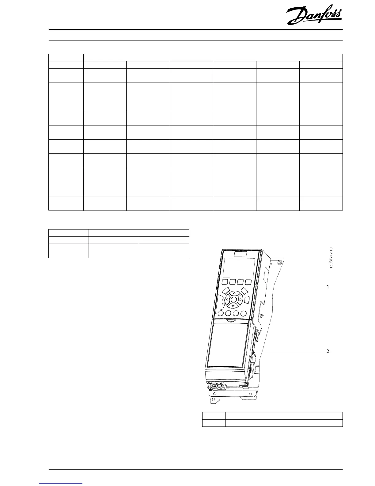
Replacing the Control Card
1LCP
2Blind cover
Illustration 1.1 LCP and Blind Cover
Installation Instructions
Control Card VLT
®
FC Series
MI93A102 Danfoss A/S © 03/2017 All rights reserved.
3
 Loading...


