Do you have a question about the Dell OptiPlex 3040 and is the answer not in the manual?
| Tcase | 71 °C |
|---|---|
| Bus type | DMI3 |
| Stepping | R0 |
| Processor cache | 6 MB |
| Processor cores | 4 |
| Processor model | i5-6500 |
| System bus rate | 8 GT/s |
| Processor family | Intel® Core™ i5 |
| Processor series | Intel Core i5-6500 Desktop series |
| Processor socket | LGA 1151 (Socket H4) |
| Processor codename | Skylake |
| Processor frequency | 3.2 GHz |
| Processor cache type | Smart Cache |
| Processor lithography | 14 nm |
| Processor manufacturer | Intel |
| Processor front side bus | - MHz |
| PCI Express slots version | 3.0 |
| Processor boost frequency | 3.6 GHz |
| Processor operating modes | 64-bit |
| ECC supported by processor | No |
| PCI Express configurations | 1x16, 2x8, 1x8+2x4 |
| Thermal Design Power (TDP) | 65 W |
| Number of processors installed | 1 |
| Maximum number of PCI Express lanes | 16 |
| Memory types supported by processor | DDR3L-SDRAM, DDR4-SDRAM |
| Memory voltage supported by processor | 1.35 V |
| Memory clock speeds supported by processor | 2133, 1333, 1600, 1866 MHz |
| Memory bandwidth supported by processor (max) | 34.1 GB/s |
| Maximum internal memory supported by processor | 64 GB |
| Non-ECC | Yes |
| Memory slots | 2x DIMM |
| Internal memory | 4 GB |
| Memory channels | Dual-channel |
| Memory clock speed | 1600 MHz |
| Internal memory type | DDR3L-SDRAM |
| Maximum internal memory | 16 GB |
| Memory layout (slots x size) | 1 x 4 GB |
| HDD speed | 7200 RPM |
| HDD interface | SATA III |
| Storage media | HDD |
| Optical drive type | DVD±RW |
| Total storage capacity | 500 GB |
| On-board graphics card ID | 1912 |
| Discrete graphics card model | Not available |
| On-board graphics card model | Intel® HD Graphics 530 |
| Maximum on-board graphics card memory | 1.74 GB |
| On-board graphics card OpenGL version | 4.4 |
| On-board graphics card base frequency | 350 MHz |
| On-board graphics card DirectX version | 12.0 |
| On-board graphics card dynamic frequency (max) | 1050 MHz |
| Number of displays supported (on-board graphics) | 3 |
| Cabling technology | 10/100/1000Base-T(X) |
| Ethernet LAN data rates | 10, 100, 1000 Mbit/s |
| HDMI version | 1.4 |
| PS/2 ports quantity | 2 |
| USB 2.0 ports quantity | USB 2.0 ports have a data transmission speed of 480 Mbps, and are backwards compatible with USB 1.1 ports. You can connect all kinds of peripheral devices to them. |
| VGA (D-Sub) ports quantity | - |
| USB 3.2 Gen 1 (3.1 Gen 1) Type-C ports quantity | 0 |
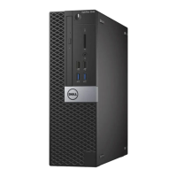
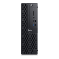
| Chassis type | SFF |
| Product color | Black |
| Placement supported | Horizontal/Vertical |
| Product type | PC |
| Motherboard chipset | Intel® H110 |
| Password protection type | BIOS, HDD, Supervisor, User |
| Compatible processor series | Intel Celeron Dual-Core, Intel Pentium Dual-Core |
| Power supply | 180 W |
| Power supply input voltage | 100 - 240 V |
| Power supply input frequency | 50 - 60 Hz |
| Operating altitude | -15.2 - 3048 m |
| Non-operating altitude | -15.2 - 10668 m |
| Storage temperature (T-T) | -40 - 65 °C |
| Operating temperature (T-T) | 5 - 35 °C |
| Storage relative humidity (H-H) | 5 - 95 % |
| Operating relative humidity (H-H) | 20 - 80 % |
| Sustainability certificates | RoHS, ENERGY STAR |
| Certification | CECP, WEEE |
| Cables included | AC |
| Scalability | 1S |
| Processor code | SR2BX |
| Processor ARK ID | 88184 |
| Processor package size | 37.5 x 37.5 mm |
| Supported instruction sets | SSE4.2, AVX 2.0, SSE4.1 |
| Thermal solution specification | PCG 2015C |
| Intel Secure Key Technology version | 1.00 |
| Depth | 292 mm |
|---|---|
| Width | 92.6 mm |
| Height | 290 mm |
| Weight | 4480 g |
A NOTE indicates important information that helps you make better use of your computer.
A CAUTION indicates potential damage to hardware or loss of data.
A WARNING indicates a potential for property damage, personal injury, or death.
Safety guidelines to protect your computer from potential damage and ensure personal safety.
Steps to properly shut down the computer before performing internal tasks.
Procedures to reconnect external devices and power after internal work.
Tools required for component removal and installation procedures.
Procedure to detach the computer's outer cover.
Procedure to reattach the computer's outer cover.
Procedure to detach the front bezel from the computer.
Procedure to reattach the front bezel to the computer.
Steps to open the front bezel door for access to internal components.
Procedure to detach the hard drive assembly from the computer.
Procedure to detach the hard drive from its mounting bracket.
Procedure to mount the hard drive into its bracket.
Procedure to reinsert the hard drive assembly into the computer.
Procedure to detach the optical drive from the computer bay.
Procedure to reinsert the optical drive into the computer bay.
Procedure to detach a 3.5-inch optical drive from the computer.
Procedure to reinsert a 3.5-inch optical drive into the computer.
Procedure to detach the SD card reader from the computer.
Procedure to reinsert the SD card reader into the computer.
Procedure to detach a memory module from the system board.
Procedure to reinsert a memory module into the system board.
Procedure to detach a PCIe expansion card from the system board.
Procedure to reinsert a PCIe expansion card into the system board.
Procedure to detach an optional Ethernet port card from the system board.
Procedure to reinsert an optional Ethernet port card into the system board.
Procedure to detach the power supply unit from the computer.
Procedure to reinsert the power supply unit into the computer.
Procedure to detach the VGA card from the computer.
Procedure to reinsert the VGA card into the computer.
Procedure to detach the intrusion switch from the computer.
Procedure to reinsert the intrusion switch into the computer.
Procedure to detach the power switch from the computer.
Procedure to reinsert the power switch into the computer.
Procedure to detach the speaker from the computer.
Procedure to reinsert the speaker into the computer.
Procedure to detach the coin cell battery from the system board.
Procedure to reinsert the coin cell battery into the system board.
Procedure to detach the heat sink assembly from the processor.
Procedure to reattach the heat sink assembly to the processor.
Procedure to detach the processor from the CPU socket.
Procedure to install the processor into the CPU socket.
Procedure to detach the system fan from the computer chassis.
Procedure to reinsert the system fan into the computer chassis.
Procedure to detach the system board from the computer.
Procedure to reattach the system board to the computer.
Diagram and identification of system board connectors and components.
Interpreting power LED status for troubleshooting computer issues.
List and description of diagnostic error messages and their solutions.
List and description of system error messages and their causes.
Configuring the order in which the computer attempts to find an operating system.
Description of keys used to navigate within the System Setup utility.
Overview of System Setup capabilities for managing hardware and BIOS options.
Steps to enter and navigate the System Setup utility.
Description of various configurable options within System Setup.
Recommended steps to update the system's BIOS for improved performance or fixes.
Information on setting and managing system and BIOS setup passwords for security.
Procedure for assigning new system and setup passwords.
Procedure for deleting or modifying existing system and setup passwords.
Details on processor and memory configurations.
Specifications for integrated video, audio, and network components.
Details on system chipset, expansion buses, and connectors.
Specifications for drives, external, and internal connectors.
Information on controls, lights, power, physical dimensions, and environmental factors.
Information on how to contact Dell for sales, technical support, or customer service.