12
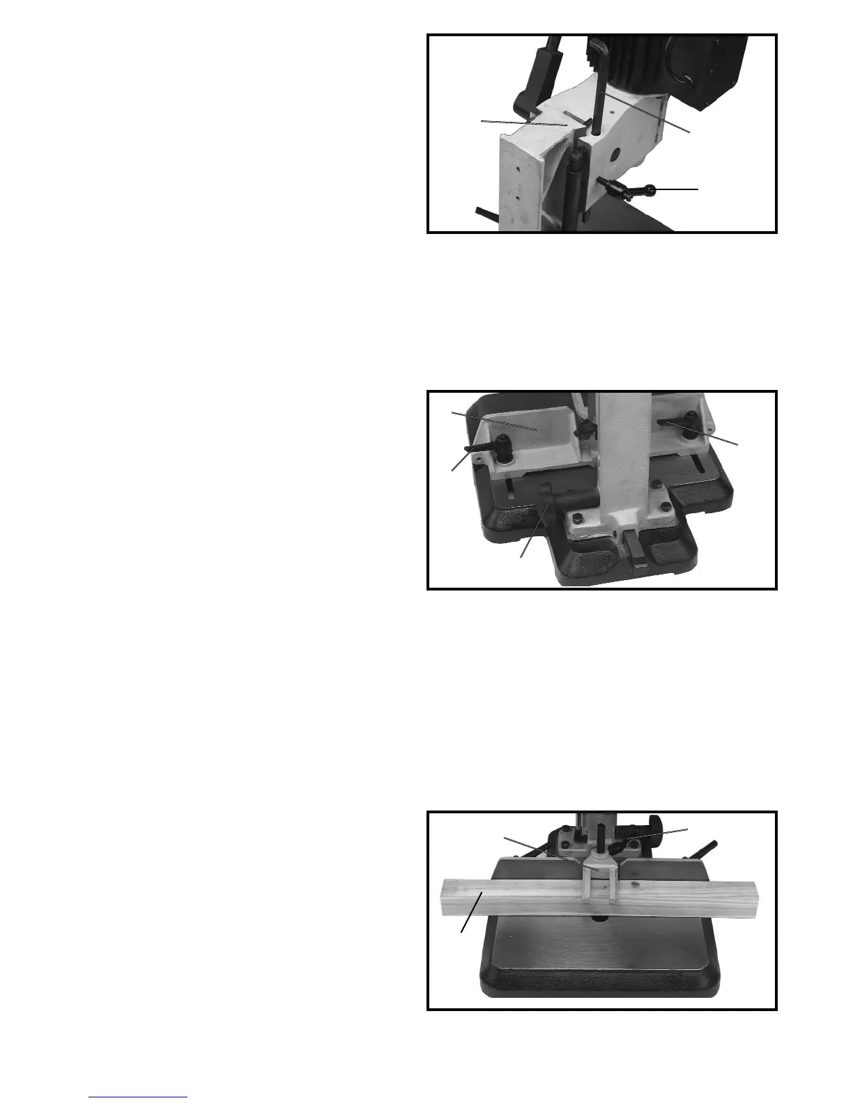
DEPTH STOP ROD
A depth stop rod (A) Fig. 23, is provided to limit the
depth of the chisel. To adjust the depth stop rod (A),
loosen lever (C) and lower head until the chisel is
at the desired depth. Lower depth stop rod (A) until it
contacts the top of the column (D) and tighten lever (C).
Fig. 23
FENCE
The fence (A) Fig. 24, can be moved in or out by
loosening lock handles (B), and rotate the fence rack
handle (C) to move the fence to the desired position and
tightening handles (B). NOTE: Levers (B) are spring-
loaded and can be repositioned by pulling out on the
lever and repositioning it on the serrated nut located
underneath the lever.
Fig. 24
Fig. 25
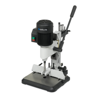
HOLDDOWN
The purpose of the holddown (C) Fig. 25, is to prevent
the workpiece (E) from lifting as the chisel is raised up,
out of the hole. The holddown (C) should be adjusted so it
just touches the top of the workpiece (E) and allows the
workpiece to slide left or right. The holddown (C) can be
turned upside down to accommodate thicker
workpieces. To adjust the holddown (C), loosen handle
(F), position holddown, and tighten handle (F).
A
D
C
B
B
A
C
C
E
F
 Loading...