18
CHANGING SPEEDS AND ADJUSTING BELT
TENSION
To reduce the risk of injury, turn unit off
and disconnect it from power source before installing
and removing accessories, before adjusting or when
making repairs. An accidental start-up can cause injury.
NOTE: Sixteen spindle speeds are available on the drill
press. A belt-positioning speed chart is located on the
inside top cover of the drill press.
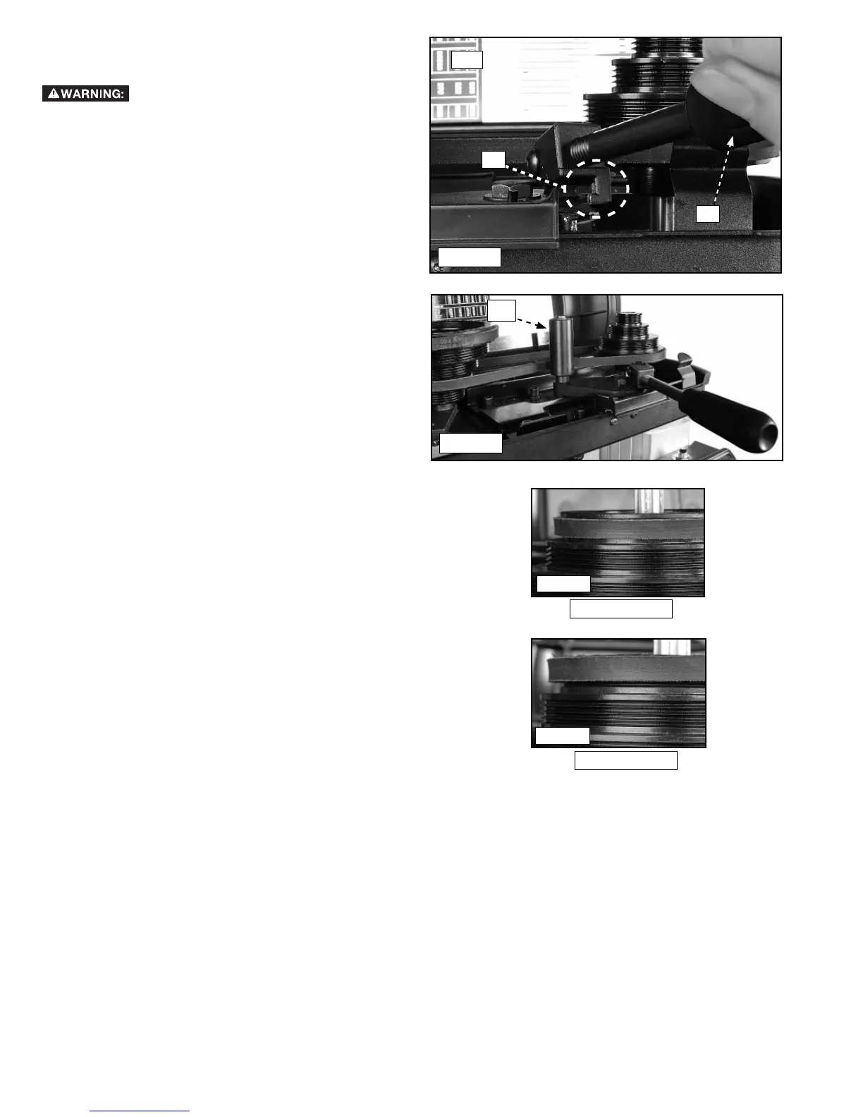
1. Lift cover (H1) Fig. 39.
2. Move belt tension lever handle (I1) Fig. 39 up and to
the right and engage the hook (J1) Fig. 39 (inset) to
hold the tensioner arm in place.
3. Choose the appropriate speed for the tool you
are using and position the belts on the pulleys
accordingly. See chart (Fig. 38) on the inside cover
of the drill press head.
4. NOTE: The belts are ribbed with grooves, so make
sure the belt grooves match up with the pulley
grooves.
5. Lift handle and move to left (as shown in Fig. 40)
until the belt tensioner arm (K1) rests against the
belts.
NOTE: Don't force the handle any further to the left. It is
set with the proper tension for the belts.
NOTE: Fig. 41 shows the proper seating for the top belt,
with the small bit of metal showing above the black belt.
Fig. 42 shows improper seating for the top belt with no
metal showing above the black belt.
Fig. 40
Fig. 39
H1
I1
Fig. 42
Fig. 41
K1
CORRECT
INCORRECT
J1
 Loading...