SV Alarm Type Alarm Output Function
2
Deviation upper-limit:
This alarm output
operates when PV value is higher than the setting value
SV+ (AL-H).
ON
SV
AL-H
3
Deviation lower-limit:
This alarm output operates when PV value is lower than the setting value
SV- (AL-L).
ON
OFF
SV
4
Reverse deviation upper- and lower-limit:
This alarm output operates when PV value is in the range of the setting
value SV+ (AL-H) and the setting value SV- (AL-L).
AL-L
SV
AL-H
5
Absolute value upper- and lower-limit:
This alarm output ope
rates when PV value is higher than the setting value
AL-H or lower than the setting value AL-L.
ON
OFF
AL-L
6
Absolute value upper-limit:
This alarm output operates when PV value is higher than the setting value
AL-H.
ON
7
Absolute value lower-limit:
This alarm output operates when PV value is lower than the setting value
AL-L.
ON
OFF
8
Deviation upper- and lower-limit with standby sequence:
This alarm output operates when PV value reaches set point (SV value)
and the value is higher than the setting value SV+(AL-
setting value SV- (AL-L).
ON
OFF
AL-L
SV
9
Deviation upper-limit with standby sequence:
This alarm output operates when PV value reaches set point (SV value)
and the reached value is higher than the setting value SV+ (AL-H).
ON
SV AL-H
10
Deviation lower-limit with standby sequence:
This alarm output operates when PV value reaches the set point (SV
value) and the reached value is lower than the setting value SV- (AL-L).
ON
OFF
AL-L SV
11
Hysteresis upper-limit alarm output:
This alarm output operates if PV value is higher than the setting value
SV+ (AL-H). This alarm output is OFF when PV value is lower than the
setting value SV+ (AL-L).
ON
AL-L
12
Hysteresis lower-limit alarm output:
This alarm output operates if PV value is lower than the setting value SV-
(AL-H). This alarm output is OFF when PV value is higher
value SV- (AL-L).
ON
OFF
Attention: AL-H and AL-L include AL1H, AL2H and AL1L, AL2L. When the 1
st
group output is set to alarm output, AL1H (1024H) and AL1L (1025H)
will be used. When the 2
nd
group output is set to alarm output, AL2H (1026H) and AL2L (1027H) will be used.
LED Display
1. When power is normal, POWER LED will be lit.
2. LED will be lit after power on. Within one second after power on, communication protocol will be displayed; and at
the following second after communication protocol displayed, communication address will be displayed. After that,
LED will all be lit to show operation is normal.
3. When control action is executing, RUN LED will be lit.
4. When input, memory, or communication happens to error, ERROR LED will be lit.
5. When output is acted, the corresponding LED will be lit.
6. When PID program is auto adjusting parameter, AT LED will blink.
7. RX LED will blink when receiving communication signal and TX LED will blink when transmitting communication
signal.
Protocol Format of LED Display When Power On
AT TX RX O1 O2 Err Run
000: 2,400bps 001: 4,800bps 010: 9,600bps
011: 19,200bps 100: 38,400bps
Parity 00: None 01: Even
10: Odd
0: ASCII
1: RTU
0:2 Stop bit
1:1 Stop bit
Communication address display: AT (bit 6) and Run (bit 0) will combine to binary code.
Password Function
The default of password will not operate. After writing 4-byte password into specific communication address, password
function will be activated. There are three levels for password protection:
1. Level1: only LED status, settings, and input values can be read via communication. It is unable to revise anything.
2. Level2: only LED status, settings, and input value can be read via communication. Also, it is able to revise setting.
3. Level3: all the settings can be read via communication, but it is only revisable for settings and AT adjustment.
4. No password function.
Once password is set (106EH ~ 1070H), the controller will enter level 1. For entering another level, please key in
corresponding password in 106BH ~ 106DH (see Address and content of Data Register). After power off, it will get back
to level one. If password protection function shall be dismissed, it is necessary to clear all password setting.
To enable password function, it is necessary to write corresponding password (106EH ~ 1070H) when password status
is dismissed. To dismiss password levels, intended password setting should be written in specific function address
106EH ~ 1070H.
Password status can be read from 106EH~1070H. Statuses corresponding to each bit are shown as the following table:
Bit b0 b1 b2 b3 b4 b5 b6
Status Level 1
Level 2
Level 3
Level 1 locked Level 2 locked Level 3 locked Unlock
Bit = 0 means no password setting. Bit = 1 means password is set (b0 ~ b2). b3 ~ b6 are used for displaying current
password status.
Synchronous Communication Protocol & Auto Number ID
By using Auto Number ID function, the communication protocol of DTC2000 can be set the same as the one of
DTC1000. ID numbers tend to increase.
1. Set the auto communication flag to be “1” for DTC1000 (communication address 1022H).
2. Switch off the controller before connecting to another DTC2000. After that, switch on the power again.
3. Communication default: 9600bps, 7bits, Even, 1 stop bit.
4. This function will result in additional 3~5 seconds for power on.
RS-485 Communication
1. Supporting transmission speed: 2,400, 4,800, 9,600, 19,200, 38,400bps.
2. Non-supported formats: 7, N, 1 or 8, E, 2 or 8, O, 2.
3. Communication protocol: Modbus (ASCII or RTU)
4. Function code: 03H to read the content of register (max. 8 words). 06H to write one word into register. 01H to read
bits data (max. 16 bits). 05H to write one bit to register.
5. Address and Content of Data Register:
Address Setting Content Explanation
Temperature unit: 0.1 degree. Analog input: 1EU.
Following read values happen to errors:
8002H: Initial process (Temperature value is not got yet)
8003H: Temperature sensor is not connected
8004H: Temperature sensor input error
8006H: Cannot get temperature value, ADC input error
1000H Process value (PV)
8007H: Memory read/write error
1001H 0 Set point (SV) Unit: 0.1 degree. Analog input: 1EU.
1002H 6,000 Upper-limit of temperature range
Upper-limit ban, unit: 0.1 degree.
1003H -200 Lower-limit of temperature range
Lower-limit ban, unit: 0.1 degree.
1004H 12 Input temperature sensor type
Please refer to the contents of the “Temperature Sensor
Type and Temperature Range” for detail
1005H 0 Control method
0: PID, 1: ON/OFF, 2: manual tuning, 3: PID program
control
1007H 4
1st group of Heating/Cooling
control cycle
0 ~ 99, 0: 0.5sec
1008H 4
2nd group of Heating/Cooling
control cycle
0 ~ 99, 0:0.5sec (it will be invalid when both groups are
control output at the same time)
1009H 476 PB Proportional band 1 ~ 9,999, unit: 0.1 degree, analog input: 1EU
100AH 260 Ti Integral time 0 ~ 9,999
100BH 41 Td Derivative time 0 ~ 9,999
100CH 0 Integration default 0 ~ 1,000, unit: 0.1%
100DH 0
Proportional control offset
error value, when Ti = 0
0 ~ 1,000, unit: 0.1%
100EH 100
COEF setting when Dual
Loop output control are used
1 ~ 9,999, unit: 0.01
100FH 0
Dead band setting when Dual
Loop output control are used
-999 ~ 9,999, unit: 0.1 degree or 1EU
1010H 0
Hysteresis setting value of the
1st output group
0 ~ 9,999, unit: 0.1 degree or 1EU
1011H 0
Hysteresis setting value of the
2nd output group
0 ~ 9,999, unit: 0.1 degree or 1EU
1012H 0
Output value read and write of
Output 1
Unit: 0.1%, write is valid only under manual control mode
1013H 0
Output value read and write of
Output 2
Unit: 0.1%, write is valid only under manual control mode
1014H 0
Upper-limit regulation of analog
linear output
1 scale = 2.8μA = 1.3mV
1015H 0
Lower-limit regulation of analog
linear output
1 scale = 2.8μA = 1.3mV
1016H 0 Temperature regulation value
-999 ~+999, unit: 0.1 degree or 1EU
1020H 0 Alarm 1 type Please see the contents of the “Alarm Outputs” for detail
1021H 0 Alarm 2 type Please see the contents of the “Alarm Outputs” for detail
1022H 0
Auto-setting communication
flag
Auto setting ban of communication: 0, auto setting of
communication: 1
1024H 40 Upper-limit alarm 1 AL1H Please see the contents of the “Alarm Outputs” for detail
1025H 40 Lower-limit alarm 1 AL1L Please see the contents of the “Alarm Outputs” for detail
1026H 40 Upper-limit alarm 2 AL2H Please see the contents of the “Alarm Outputs” for detail
1027H 40 Lower-limit alarm 2 AL2L Please see the contents of the “Alarm Outputs” for detail
102AH Read/Write status b1: ALM2, b2:
o
C, b3:
o
F, b4: ALM1, b5: O2, b6:O1, b7: AT
102CH 0
Setting of positive/negative
proportional output
0: positive, 1: negative
102EH LED status b0: RUN, b1: ERR, b2: O2, b3: O1, b4: RX, b5:TX b6: AT
102FH Software version V1.00 indicates 0x100
1030H 0 Start pattern number 0 ~ 7
1032H
Remaining time of read
execution
Unit: second
1033H
Remaining time of reading
execution step
Unit: minute
1034H
Step number of reading
current execution step
0 ~ 7
1035H
Executing number of reading
current pattern
0 ~ 7
1037H 1,000
Upper-limit of proportional
output
0 ~ 100% max. analog output is upper limit, unit: 0.1%
1038H 0
Lower-limit of proportional
output
0 ~ 100% max. analog output is lower limit, unit: 0.1%
1040H~
1043H
7
Actual step number setting
inside the correspond pattern
0 ~ 7 = N means the pattern is executed from step from 0
to N.
1050H~
1053H
0
Cycle number of repeating
executing pattern 0 ~ 7
0 ~ 199 means the pattern is executed for 1 ~ 200 times.
1060H~
1063H
0
Link pattern number setting of
the current pattern
0 ~ 8, 8 means program end. 0 ~ 7 means the next
execution number after completing current pattern.
1068H 1 Control execution/Stop setting 0: Stop, 1: execute, 2: program end, 3: program hold
1069H 0 Output 1: control selection 0: heating, 1: cooling, 2: alarming, 3: proportional output
106AH 0 Output2: control selection 0: heating, 1: cooling, 2: alarming
106BH 0
Dismiss level 1
Read/write allowed
Shall be same as level 1 password setting (106E)
106CH 0 Dismiss level 2. Use level 3. Shall be same as level 2 password setting (106F)
106DH 0 Dismiss level 3. Use level 2 Shall be same as level 3 password setting (1070)
106EH 0 Dismiss level 1/Set password Clear old password before new password setting
106FH 0 Dismiss level 2/Set password Clear old password before new password setting
1070H 0 Dismiss level 3/Set password Clear old password before new password setting
1071H 1
Read/Write communication
address
1 ~ 247
1072H 0
Read/Write communication
format
RTU: 1, ASCII: 0
1073H 2
Baud rate setting of
communication
0 ~ 4: 2,400 ~ 38,400
1074H 1
Data length setting of
communication
0: 8bit 1: 7bit
1075H 1 Parity bit setting 0: None 1:Even 2: Odd
1076H 1 Stop bit setting 0: 2 stop bit 1: 1stop bit
Address Setting Content Explanation
2000H~
203FH
0
Pattern 0 ~ 7 to set target
temperature
Pattern 0: 2000H ~ 2007H
Temperature measure unit: 0.1 degree
2080H~
20BFH
0
Pattern 0~7 to set execution
time.
Pattern 0: 2080H ~ 2087H
Time 0 ~ 900 (1 minute for each scale)
6. Address and Content of Bit Register: ( First bit of reading will put into LSB, Write data = FF00H for bit set, 0000H
for bit data as “0”)
0811H Temperature unit display selection 0:
o
F, 1 :
o
C (default)
0813H AT setting AT setting OFF: 0 (default), AT setting ON: 1
0814H Control RUN/STOP setting 0: STOP, 1: Execute (default)
0815H Program hold flag 1: Program temporary stop
0816H Program stop flag 1: Program stop
7. Communication format: 01: read bit data, 05: write bit data, 03: read word, 06: write word.
ASCII Mode:
To Read Instruction
To Read Response
Message
To Write Instruction
To Write Response
Message
Starting word
’:’
’:’
Starting word
’:’
’:’
Starting word
’:’
’:’
Starting word
’:’
’:’
Machine
address 1
‘0’
‘0’
Machine address
1
‘0’
‘0’
Machine
address 1
‘0’
‘0’
Machine
address 1
‘0’
‘0’
Machine
address 0
‘1’
‘1’
Machine address
0
‘1’
‘1’
Machine
address 0
‘1’
‘1’
Machine
address 0
‘1’
‘1’
Instruction 1
‘0’
‘0’
Instruction 1 ‘0’
‘0’
Instruction 1
‘0’
‘0’
Instruction 1
‘0’
‘0’
Instruction 0
‘3’
‘1’
Instruction 0 ‘3’
‘1’
Instruction 0
‘6’
‘5’
Instruction 0
‘6’
‘5’
‘1’
‘0’
‘0’
‘0’
‘1’
‘0’
‘1’
‘0’
‘0’
‘8’
Response data
length (byte)
‘4’
‘2’
‘0’
‘8’
‘0’
‘8’
‘0’
‘1’
‘0’
‘1’
‘0’
‘1’
‘0’
‘1’
To read
data/Staring
word address
‘0’
‘0’
‘1’
‘7’
To write data
address
‘1’
‘0’
To write data
address
‘1’
‘0’
‘0’
‘0’
‘F’
‘0’
‘0’
‘F’
‘0’
‘F’
‘0’
‘0’
Data content of
1000H/081xH
‘4’
‘1’
‘3’
‘F’
‘3’
‘F’
‘0’
‘0’
‘0’
‘E’
‘0’
‘E’
‘0’
To read data
length/Word
length
(word/bit)
‘2’
‘9’
‘0’
To write data
content
‘8’
‘0’
To write data
content
‘8’
‘0’
LRC1 check
‘E’
‘D’
‘0’
LRC1 ‘F’
‘E’
LRC1 ‘F’
‘E’
LRC 0 check
‘A’
‘D’
Data content of
1001H
‘0’
LRC 0 ‘D’
‘3’
LRC 0 ‘D’
‘3’
Ending word 1
CR
CR
LRC1 check
‘0’
‘E’
Ending word 1
CR
CR
Ending word 1
CR
CR
Ending word 0
LF
LF
LRC 0 check ‘3’
‘4’
Ending word 0
LF
LF
Ending word 0
LF
LF
Ending word 1
CR
CR
Ending word 0
LF
LF
LRC Check:
LRC check is the added sum from “Machine Address” to “Data content”. For example, 01H + 03H + 10H+ 00H + 00H + 02H
= 16H, then take the complementary of 2 to get EA.
RTU Mode:
To Read Instruction
To Read Response
Message
To Write Instruction
To Write Response
Message
Machine
address
01H
01H
Machine address
01H
01H
Machine
address
01H
01H
Machine
address
01H
01H
Instruction 03H
01H
Instruction 03H
01H
Instruction 06H
05H
Instruction 06H
05H
10H
08H
10H
08H
10H
08H
Starting
address of
reading data
00H
10H
Response data
length (byte)
04H
02H
To write data
address
01H
10H
To write data
address
01H
10H
00H
00H
01H
17H
03H
FFH
03H
FFH
To read data
length
(word/bit)
02H
09H
Data content 1
F4H
01H
To write data
content
20H
00H
To write data
content
20H
00H
CRC low byte
C0H
BBH
03H
CRC low byte
DDH
8FH
CRC low byte
DDH
8FH
CRC high byte
CBH
A9H
Data content 2
20H
CRC high byte
E2H
9FH
CRC high byte
E2H
9FH
CRC low byte
BBH
77H
CRC high byte
15H
88H
Following is a CRC (Cyclical Redundancy Check) program example:
unsigned int reg_crc = 0xffff; i = 0;
while (length--)
{
reg_crc ^= RTUData[i];
i ++;
for (j = 0; j < 8; j++)
{
if (reg_crc & 0x01) reg_crc = (reg_crc >> 1) ^ 0xA001;
else reg_crc = reg_crc >> 1;
}
}
return(reg_crc);
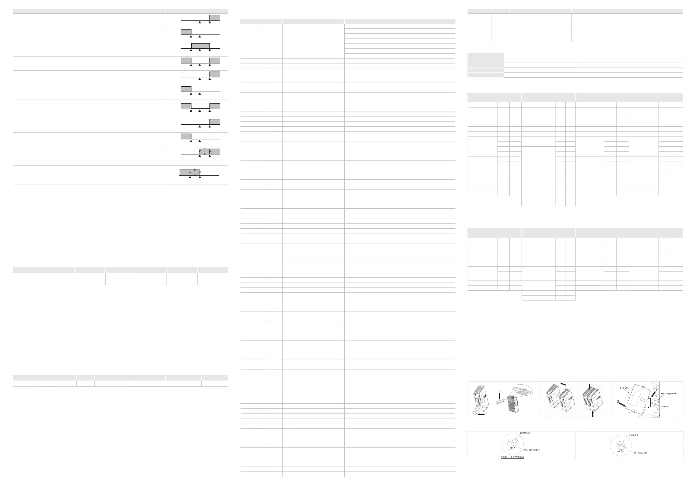
Installation
DTC modules can be expanded up to 8, and installed with DIN rail mounting
How to Set Up Current Input
For normal input For current input (4 ~ 20mA, 0 ~ 20mA)
PIN HEADER
JP1
DEFAULT SETTING
PIN HEADER
JP1
The content of this instruction sheet may be revised without prior notice. Please consult our distributors or download the most
updated version at http://www.delta.com.tw/industrialautomation

 Loading...