6
2. When you use INA input or INA + INB input, set up relevant parameters using the table below.
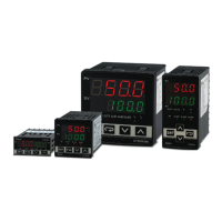
INA input:
INA CH1 CH2 CH3 CH4
OUT1 control mode 10A8H 10A9H 10AAH 10ABH
OUT2 control mode 10B0H 10B1H 10B2H 10B3H
Alarm 1 output mode 10C0H 10C1H 10C2H 10C3H
Alarm 2 output mode 10C4H 10C5H 10C6H 10C7H
Upper bound of Alarm 1 output 1080H 1081H 1082H 1083H
Lower bound of Alarm 1 output 1088H 1089H 108AH 108BH
Upper bound of Alarm 2 output 1084H 1085H 1086H 1087H
Lower bound of Alarm 2 output 108CH 108DH 108EH 108FH
CT value(latch)
19A0H 19A1H 19A2H 19A3H
CT value(dynamic)
19A4H 19A5H 19A6H 19A7H
CT adjustment value
19A8H
19A9H 19AAH 19ABH
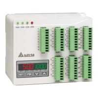
INA + INB input:
INA+INB CH1 CH2 CH3 CH4 CH5 CH6 CH7 CH8
OUT1 control mode 10A8H 10A9H 10AAH 10ABH 10ACH 10ADH 10AEH 10AFH
Alarm 1 output mode 10C0H 10C1H 10C2H 10C3H 10C4H 10C5H 10C6H 10C7H
Upper bound of Alarm 1 output 1080H 1081H 1082H 1083H 1084H 1085H 1086H 1087H
Lower bound of Alarm 1 output 1088H 1089H 108AH 108BH 108CH 108DH 108EH 108FH
CT value(latch)
19A0H 19A1H 19A2H 19A3H -- -- -- --
CT value(dynamic)
19A4H 19A5H 19A6H 19A7H -- -- -- --
CT adjustment value
19A8H
19A9H 19AAH 19ABH -- -- -- --
3. OUT1 control mode has to be set to “0” (heating) or “1” (cooling). It cannot be set to “2” (proportional output).
4. You can select Alarm 1 or Alarm 2 to be the output contact. The output mode has to be set to “13” (000DH).
5. Adjust the upper/lower bound of the alarm output.
6. The CT value will only be measured when there is OUT1 executing. If OUT1 does not exist, the previous CT value measured will be
displayed.
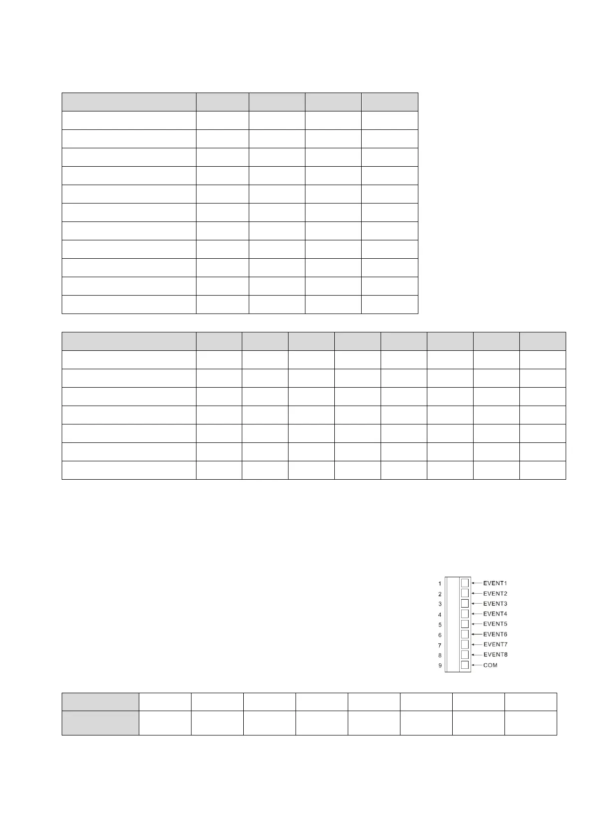
EVENT Input
Function:
DTE10T offers 8 channels of EVENT input (EV1 ~ EV8), and each EVENT can be set up independently.
Slot number 1 ~ 8 in AUX on DTE10T correspond to EV1 ~ EV8.
EV1 to EV8 can be short-circuited individually with slot number 9 to switch functions.
Hardware requirement: Accessory DTE20D inserted in the slot AUX.
How to operate:
1. Enable the EVENT function: Write 1234H into the address 47F1H and then 0002H into address 4824H.
Bits in 4824H Bit7 Bit6 Bit5 Bit4 Bit3 Bit2 Bit1 Bit0
Flag --
Hot runner
control
Slop
control
-- Latch CT EVENT --
Notes:
The flag to enable EVENT is at bit1 of 4824H. Write 0002H to bit1 to set it on.
If the “multistate” function is enabled, for example, writing in 0022H means enabling bit5 and bit1 at the same time.
You can only choose to use either the CT or EVENT function.
 Loading...