- 1 -
………………………………………………………………… ENGLISH …………………………………………………………………
Thank you for choosing DELTA DVP PLC Series. DVP08TC-H2 is able to receive 8
points 0~150mV voltage input of thermocouple temperature sensors (J-type, K-type,
R-type, S-type, T-type, E-type, N-type) and convert them into 24-bit digital signals.
Besides, through FROM/TO instructions in DVP-EH2 MPU program, the data in
DVP08TC-H2 can be read or written. There are 49 16-bit control registers (CR) in it.
DVP08TC-H2 displays temperatures in Celsius (resolution: 0.1°C) and Fahrenheit
(resolution: 0.1°F).
EN DVP08TC-H2 is an OPEN-TYPE device. It should be installed in a control cabinet
free of airborne dust, humidity, electric shock and vibration. To prevent
non-maintenance staff from operating DVP08TC-H2, or to prevent an accident
from damaging DVP08TC-H2, the control cabinet in which DVP08TC-H2 is
installed should be equipped with a safeguard. For example, the control cabinet
in which DVP08TC-H2 is installed can be unlocked with a special tool or key.
EN DO NOT connect AC power to any of I/O terminals, otherwise serious damage
may occur. Please check all wiring again before DVP08TC-H2 is powered up.
After DVP08TC-H2 is disconnected, Do NOT touch any terminals in a minute.
Make sure that the ground terminal
on DVP08TC-H2 is correctly grounded in
order to prevent electromagnetic interference.
FR DVP08TC-H2 est un module OUVERT. Il doit être installé que dans une enceinte
protectrice (boitier, armoire, etc.) saine, dépourvue de poussière, d’humidité, de
vibrations et hors d’atteinte des chocs électriques. La protection doit éviter que
les personnes non habilitées à la maintenance puissent accéder à l’appareil (par
exemple, une clé ou un outil doivent être nécessaire pour ouvrir a protection).
FR Ne pas appliquer la tension secteur sur les bornes d’entrées/Sorties, ou l’appareil
DVP08TC-H2 pourra être endommagé. Merci de vérifier encore une fois le
câblage avant la mise sous tension du DVP08TC-H2. Lors de la déconnection de
l’appareil, ne pas toucher les connecteurs dans la minute suivante. Vérifier que la
terre est bien reliée au connecteur de terre afin d’éviter toute interférence
électromagnétique.
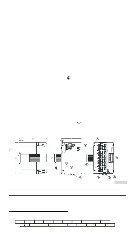
Product Profile & Dimension
Unit: mm [inch] [Figure 1]
1. DIN rail (35mm) 6. Terminals
2. Connection port for extension module 7. Mounting hole
3. Model name 8. I/O terminals
4. POWER, ERROR, A/D indicator 9. Mounting port for extension module
5. DIN rail clip
I/O Terminal Layout
24V
0V
L -
L+
Ch8
Ch7Ch6Ch5Ch4
L+L+L+L+
L+
L+L+
L -L -L -L -L -L -L -
Ch3Ch2Ch1
SLD
 Loading...