Controller
Instruction Sheet
1 WARNING
This Installation Sheet only provides descriptions for electrical specifications, function specifications,
installation & wiring, troubleshooting and peripherals. Other detail infromation about programming and
instructions, please see PLC Application Manual. For more information about the optional peripherals,
please refer to their individual instruction sheet or user manuals.
This is an OPEN TYPE PLC. The PLC should be kept in an enclosure away from airborne dust, high
humidity, electric shock risk and vibration. Also, it should be equipped with protective methods such as
some special tools or keys to open the enclosure, so as to avoid the hazard to users and the damage to
the PLC. The power must be OFF before any maintenance.
Never connect the AC main circuit power supply to any of the input/output terminals, as it will damage the
PLC. Check all the wiring prior to power up. To avoid any electromagnetic noise, make sure the PLC is
properly grounded
. Do NOT touch terminals when power on.
2 INTRODUCTION
2.1. Model Name Explanation and Peripherals
Thank you very much for purchasing Delta’s DVP-ES/EX Series PLC. DVP-ES/EX Series provide the main
processing units and extension units. The processing units offer 14~60 points and the extension units offer 8~32
points. The maximum input and output can be extended up to 128 points respectively. Also, it can be used on
various applications according to input and output points, power supply, digital input and output modules.
Nameplate Explanation
PLC Model
Input Power Supply Spec.
Output Module Spec.
Barcode and Se rial Number
MCU Version
100~24 0Vac 50/60Hz 35VA M AX
2.0A 240Vac 50/60Hz RES LOA D
32ES00R 2T514000 4
VX.XX
32ES00R 2 T 5 14 0004
Production series
Production week
Production year (2005)
Production plant (Taoyuan)
Serial number of version
Production Model
Model/Serial Number Explanation
DVP
2
E
: Main Processing Unit (MPU)
X
: Exten si on Unit
S
: Sta ndard
X
: A/D, D/A Functions
M
: Digital Input
N
: Dig ital Output
P
: Digital Input/Output
2
: Adv anced Type
R
: Re la y
T
: Transistor
N
: No Output Module
00 :
H TYPE
01
:
L TYPE
11
:
H TYPE
C
: Non-extended
Product Series
Points (Input + Output)
Models
Model Type
AC Input DC Inp ut DC Input
Peripherals
◎ DVP-HPP Series: Handheld Programmable Panel
◎ WPLSoft: DVP-PLC Programming Software Tool (Windows based software)
◎ DVPACAB115: 1.5M Cable (HPP PLC, provided in DVP-HPP Series)
◎ DVPACAB215: 1.5M Cable (PC PLC)
◎ DVPACAB230: 3.0M Cable (PC PLC)
◎ DVPACAB315: 1.5M Cable (HPP PC)
◎ DVPACAB403: 30cm Cable (Main processing unit Extension unit, or Extension unit Extension I/O
signal extension cable)
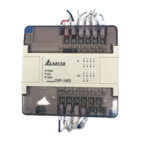
2.2. Product Profile and Outline
1. DIN rail clip 9. Input / Output
2. DIN rail (35mm)
10. Status indicators: POWER, RUN, and
ERROR
3. Direct mounting holes 11. Input / Output terminal cover
4. Communication Ports Cover (RS-232C) 12. Input / Output terminal cover
5. Extension Port indicators
13. Input / Output terminal nameplate
panel
6. Input / Output terminals
14. Input / Output terminal nameplate
panel
7. Input / Output terminals 15. RS-485 communication port
8. Input / Output indicators
2.3. DVP-ES/EX Series Models
◎ ES Standard Main Processing Units (MPU-00)
Input Unit Output Unit
Model Name Power
Point Type Point Type
Profile Profile Reference
DVP14ES00R2 8 6
DVP24ES00R2 16 8
DVP32ES00R2 16 16
DVP40ES00R2 24 16
DVP60ES00R2 36 24
Relay
DVP14ES00T2 8 6
DVP24ES00T2 16 8
DVP32ES00T2 16 16
DVP40ES00T2 24 16
DVP60ES00T2
100~
240
VAC
36
DC Sink
or
Source
24
Transistor
◎ ES Standard Main Processing Units (MPU-01,11)
Input Unit Output Unit
Model Name Power
Point Type Point Type
Profile
DVP14ES01R2 8 6
DVP24ES01R2 16 8
DVP24ES11R2 16 8
DVP32ES01R2 16 16
Relay
DVP14ES01T2 8 6
DVP24ES01T2 16 8
DVP32ES01T2
24
VDC
16
DC Sink
or
Source
16
Transistor
◎ EX Special Function Main Processing Units (MPU-00, MPU-11)
Input Unit Output Unit
Point Type Point Type
Model Name Power
DI AI DI AI DO AO DO AO
Profile Reference
DVP20EX00R2 8 4 6 2 Relay
DVP20EX00T2
100~
240
VAC
8 4 6 2 Transistor
DVP20EX11R2
24
VDC
84
DC Sink
or
Source
-20mA~20
mA
or
-10V ~ +10
V
6 2 Relay
0~20mA
or
0~10V
◎ Digital I/O Extension Unit for DVP-ES/EX Series- 00
Input Unit Output Unit
Model Name Power
Point Type Point Type
Profile Reference
DVP24XN00R 0 24
DVP24XP00R 16 8
DVP32XP00R 16 16
Relay
DVP24XN00T 0 24
DVP24XP00T 16 8
DVP32XP00T
100~
240
VAC
16
DC
Sink
or
Source
16
Transistor
◎ Digital I/O Extension Unit for DVP-ES/EX Series- 01 (L TYPE)
Input Unit Output Unit
Model Name Power
Point Type Point Type
Profile Profile Reference
DVP16XM01N 16 0 None
DVP16XN01R 0 16
DVP24XN01R 0 24
DVP24XP01R 16 8
DVP32XP01R 16 16
Relay
DVP16XN01T 0 16
DVP24XN01T 0 24
DVP24XP01T 16 8
DVP32XP01T
24
VDC
16
DC
Sink
or
Source
16
Transistor
◎ Digital I/O Extension Unit for DVP-ES/EX Series-11 (H TYPE)
Input Unit Output Unit
Model Name Power
Point Type Point Type
Profile Profile Reference
DVP08XM11N 8 0
DVP16XM11N 16 0
None
DVP08XN11R 0 8
DVP16XN11R 0 16
DVP24XN11R 0 24
DVP08XP11R 4 4
DVP24XP11R 16 8
DVP32XP11R 16 16
Relay
DVP08XN11T 0 8
DVP16XN11T 0 16
DVP24XN11T 0 24
DVP08XP11T 4 4
DVP24XP11T 16 8
DVP32XP11T
24
VDC
16
DC
Sink
or
Source
16
Transistor
3 SPECIFICATIONS
3.1. Function Specifications
Items Specifications Remarks
Control Method
Stored program, cyclic scan system
I/O Processing Method
Batch processing (when END instruction
is executed)
I/O refresh instruction is available
Execution Speed
Basic commands (several us)
Application instructions
(10 ~ hundreds us)
Program Language
Instruction, Ladder Logic, SFC Including Step instructions
Items Specifications Remarks
Program Capacity
3792 Steps Built-in EEPROM
Instructions
32 basic sequential instructions
(including STL / RET)
107 application instructions
Initial Step Point
10 points S0~S9
Zero Return Point
10 points S10~S19
Step Relays
(Latched)
General Step Point
108 points S20~S127
General
512+232 points M0~M511+M768~M999
Latched
256 points M512~M767
Auxiliary
Relays
Special
280 points M1000~M1279
64 points T0~T63 (100 ms time base)
63 points
T64~T126 (10 ms time base, when
M1028 is ON)
Timers Digital
1 points T127 (1 ms time base)
General
112 points C0~C111
Latched
16 points C112~C127
Counters
High Speed
13 points 1 phase 20KHz, 2 phase 5KHz C235~C254 (all latched type)
General
408 points D0 ~ D407
Latched
192 points D408~D599
Data Registers
Special
200 points
D1000~D1143、D1256~D1311
Pointers P
64 points P0~P63
Index Registers E / F
2 points
E(=D1028),F(=D1029)
Decimal K
16 bit: -32768~+32767 32 bit: -2147483648~+2147483647
Constants
Hexadecimal H
16 bit: 0000~FFFF 32 bit: 00000000~FFFFFFFF
Serial Communication
2 Ports is provided. RS-232C: Program read/write communication port,
RS-485: General function communication port (controlled by RS instruction);
Special drive instructions for Delta AC drive are also supported.
Protection Features
Password, I/O examination, Execution time, Illegitimate instruction or operand
Monitor / Debug
Program execution time display, Bit/Word, Device setting
* Note: For more information about special relays and data registers, please refer to the Delta PLC Application Manual.
3.2. Electrical Specifications
Model
Item
DVP-
14ES00
□
DVP-
24ES00
□
DVP-
32ES00
□
DVP-
40ES00
□
DVP-
60ES00
□
DVP-
20EX00
□
DVP-
14ES01
□
DVP-
24ES□□
DVP-
32ES01
□
DVP-
20EX11□
Power Supply
Voltage
100~240VAC (-15%~10%), 50/60Hz ± 5%
24VDC (-15%~10%)
Operation
Specification
The PLC start to operate at power supply of 95~100VAC.
If the voltage of power supply drops to 70VAC, the PLC will stop.
Maximum power loss time is 10ms or less.
Maximum power loss time is 5ms or less.
Fuse
2 A / 250VAC 2 A / 250VAC
Power
Consumption
20 VA 25VA 30VA 30VA 35VA 30 VA 5.5 W 6.5 W 8 W 8 W
DC24V Supply
Current
400mA 400mA 400mA 400mA 400mA 400mA
— — — —
Power
Protection
DC24V output short circuit DC24V input polarity
Voltage
Withstand
1500VAC(Primary-secondary), 1500VAC(Primary-PE), 500VAC(Secondary-PE)
Insulation
Resistance
> 5 MΩ at 500VDC (Between all inputs / outputs and earth)
Noise Immunity
ESD: 8KV Air Discharge
EFT: Power Line: 2KV, Digital I/O: 1KV, Analog & Communication I/O: 250V
RS: 26MHz~1GHz, 10V/m
Grounding
The diameter of grounding wire cannot be smaller than the wire diameter of terminals L and N (All DVP units
should be grounded directly to the ground pole).
Environment
Operation: 0°C ~55°C (Temperature), 50~95% (Humidity), Pollution degree2; Storage: -25°C ~70°C
(Temperature), 5~95% (Humidity)
Vibration / Shock
Resistance
Standard: IEC1131-2, IEC 68-2-6(TEST Fc)/ IEC1131-2 & IEC 68-2-27 (TEST Ea)
Weight (g)
400 552 580 596 750 536 260 414 430 386
Input Point Electrical Specifications
Input Point Type
Digital Input Analog Input (EX)
Input Type
DC (SINK or SOURCE)
Input Current
24VDC 5mA
Voltage input: -10V~+10V, Input Resistance:
112 KΩ
Current input: -20mA~+20mA, Input
Resistance: 250Ω
Off→On above 16VDC
Active Level
(Analog input resolution)
On→Off below 14.4VDC
Voltage input: 10bit
Current input: 10 bit
Reaction Time
(Conversion Sampling Time)
About 10ms (An adjustment range of 0~15ms
could be selected through D1020 and D1021)
5ms (Time could be adjusted through D1118)
Output Point Electrical Specifications
Output Point Type
Relay-R Transistor-T
Current Specification
2A/1 point (5A/COM)
55°C 0.1A/1point, 50°C 0.15A/1 point
45°C 0.2A/1 point, 40°C 0.3A/1 point (2A/COM)
Voltage Specification
Below 250VAC, 30VDC 30VDC
75VA (Inductive)
Maximum Load
90 W (Resistive)
9W/1 point
Reaction Time
About 10 ms
Off→On 20us On→Off 30us
3.3. AD/DA Specifications
Analog Input (A/D) Analog Output (D/A)
Items
Voltage Input Current Input Voltage Output Current Output
Analog I/O Range
±10V ±20 mA 0 ~ 10V 0 ~ 20 mA
Digital Conversion
Range
-512~+511 -512~+511 0 ~ 255 0 ~ 255
Resolution
10 bits(1
LSB
=19.53125 mV) 10 bits (1
LSB
=39.0625 μA) 8 bits(1
LSB
=39.0625 mV) 8 bits (1
LSB
=78.125 μA)
Input Impedance
> 112 KΩ 250Ω -