1
3
4
5
6
7 8
2
F60.0 will be displayed on the screen.
Press the enter button.
00. will appear on the screen.
Press enter again.
00.00 will appear on the screen.
Use the up and down keys to change parameters
selections to the desired one. Press "ENTER"
You will now be able to change the parameter to the
desired value or setting. Press enter. End will flash
on your screen to indicate that your setting has
been saved.
Continue the above steps till all of your parameters
have been set.
Once all the parameters have been set press the
"MODE" button till the F50.0 screen comes up again.
00.02 All parameters are reset to factory settings
for 50Hz, set to 9 (must be none after initial power
up)
00.20 Source of master Frequency Command.
00.21 Source of master Operation Command.
01.00 Change to the maximum Frequency
required
01.01 Change value to match Hz on motor name
plate
01.02 Change to match voltage on motor name
plate (Max Voltage output)
01.10 Upper limit Frequency
01.11 Lower limit Frequency
01.12 Acceleration time (factory setting 10sec)
01.13 Deceleration time (factory setting 10sec)
05.01 Set to Motor Name Plate Current
05.02 Set to Motor Name Plate kW
05.03 Set to Motor Name Plate Speed (rpm)
05.04 Set as the number of poles of the
motor(3000rpm=2pole; 1500rpm=4pole;
1000rpm=6pole; 750rpm=8pole)
05-00 Auto tuning, option 1 Dynamic test for
induction motor = 1 (note motor must be
unloaded), Static test for induction motor = 2,
after the parameter number is entered press
MODE button to return to main screen showing
F30.00 or F33.33, press the RUN button to start
auto tune, these test should only be preformed
after all the above data is entered.
List of quick set parameters
0 = UP/DOWN arrow (Factory setting)
2 = External analog input
3 = External UP/DOWN terminals
7 = Digital keypad potentiometer
0 = Digital keypad (Factory setting )
1 = External terminals
See back page for remote control set up
Wiring and connection must be carried out by
a registered electrician.
Connection by an unqualified person voids
the warranty.
Please check the suitability of the motor
before attempting to connect it to the device.
Ensure the motor terminals are configured to
suit supply from VSD, for 1ph supply VFD the
motor must be connected in DELTA. For 3ph
supply VFD please consult the motors name
tag for 400V connection.
Important Notice
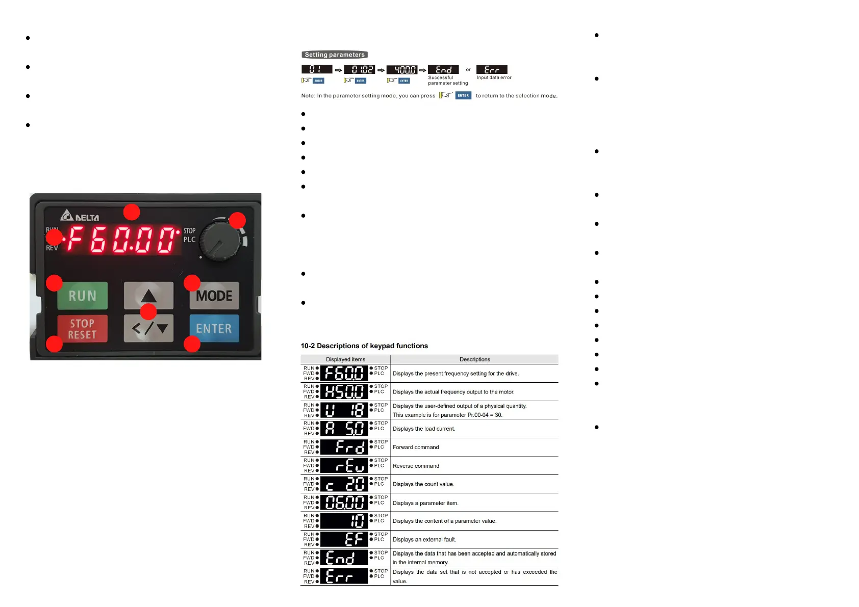
Status Display –Display the drives current status
LED Display—Indicates frequency, voltage, current,
user defined units
Potentiometer—For local frequency control
Run Key— to start drive locally
UP & DOWN Key—Used to change numerical
numbers, frequency, parameters
Mode—Change between different display mode
STOP/RESET— Stops AC drive operation and
resets the drive after a fault has occurred
ENTER - Used to enter and save the parameters
1.
2.
3.
4.
5.
6.
7.
8.
Quick Setup for Variable Speed Drive
Turn on power to unit and follow as below:
FOR ADVANCED SET UP REFFER TO THE FULL
MANUAL
www.rotatingmachinery.co.nz/products/drives
 Loading...