7
RCD-M37 / RCD-M37DAB / D-E500 / D-M37
DISASSEMBLY
• Disassemble in order of the arrow of the figure of following flow.
下記フロー図の矢印の順番にはずしてください。
• In the case of the re-assembling, assemble it in order of the reverse of the following flow.
再組み立ての場合は、下記のフローの逆の順番に組立ててください
• In the case of the re-assembling, observe "attention of assembling" it.
再組み立ての場合は、「組立のご注意」を遵守してください。
TOP CABINE
LOADER PANE
REAR PANEL SUB ASS
Refer to "DISASSEMBLY Refer to "DISASSEMBLY
1.LOADER PANEL" 6.REAR PANEL SUB ASSY"
and "EXPLODED VIEW" and "EXPLODED VIEW"
SUB TRANS UNIT
FRONT PANEL SUB ASS
(Ref. No. of EXPLODED VIEW : C6)
Refer to "DISASSEMBLY INPUT P.W.B UNIT ASSY
2.FRONT PANEL SUB ASSY" (Ref. No. of EXPLODED VIEW : C8)
and "EXPLODED VIEW" DAB MODULE
FRONT UNIT (Ref. No. of EXPLODED VIEW : C9)
(Ref. No. of EXPLODED VIEW : C1) TUNER MODULE
(Ref. No. of EXPLODED VIEW : C12)
CD MECH
SPK UNIT
Refer to "DISASSEMBLY Refer to "DISASSEMBLY 7.SPK UNIT"
3.POWER SUPPLY UNIT" and "EXPLODED VIEW"
and "EXPLODED VIEW" SPK UNIT
(Ref. No. of EXPLODED VIEW : C7)
HEAT SINK SUB ASS
MCU P.W.B UNIT ASS
GUIDE UNIT
Refer to "DISASSEMBLY Refer to "DISASSEMBLY Refer to "DISASSEMBLY 8.GUIDE UNIT"
5.HEAT SINK SUB ASSY" 4.MCU P.W.B UNIT ASSY" and "EXPLODED VIEW"
and "EXPLODED VIEW" and "EXPLODED VIEW" GUIDE UNIT
AMP UNIT MCU P.W.B UNIT ASSY (Ref. No. of EXPLODED VIEW : C5)
(Ref. No. of EXPLODED VIEW : C4) (Ref. No. of EXPLODED VIEW : C2)
TRANS
Refer to "DISASSEMBLY 9.TRANS"
and "EXPLODED VIEW"
TRANS
(Ref. No. of EXPLODED VIEW : C11)
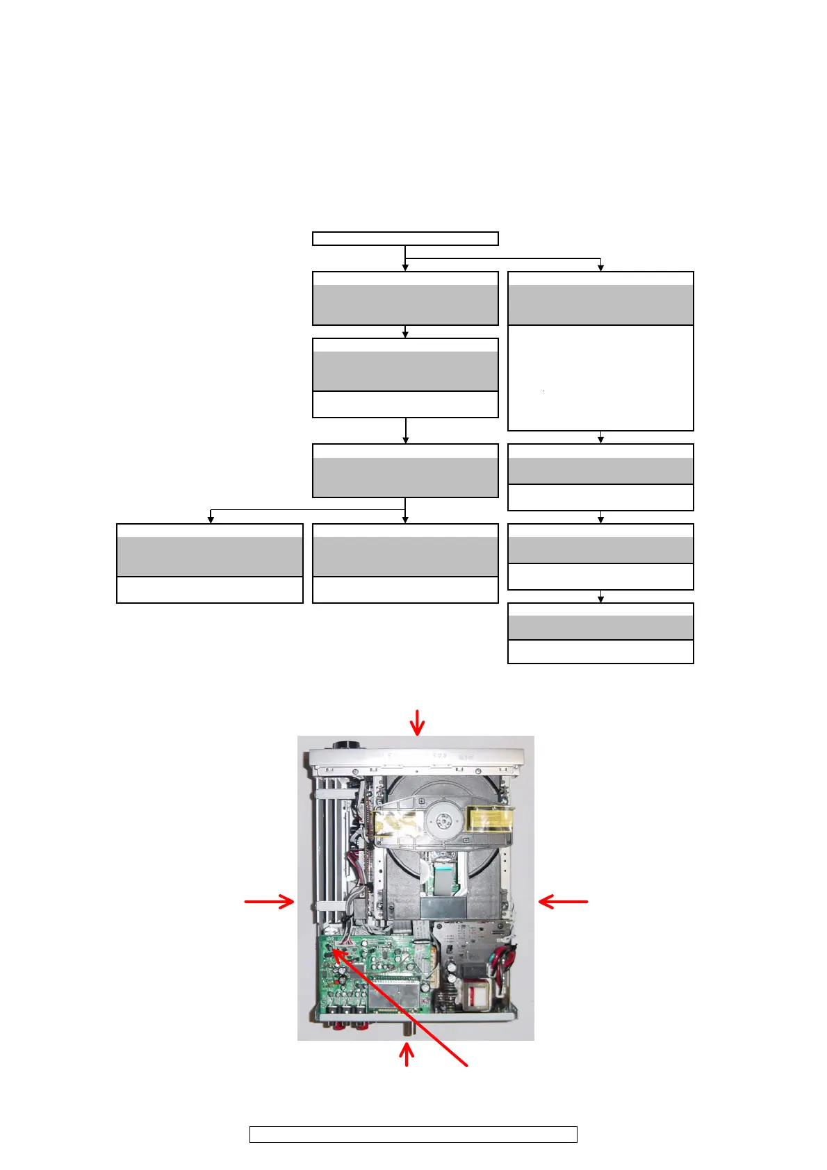
Front side
Picture B
Picture E
Picture A
Picture C
Picture D
Top view
The viewpoint of each photograph
(photography direction)
各図の視点(撮影方向)
 Loading...