ENGLISH
5
12
3
18
D25831
D25501, D25601,
D25603, D25820
3
12
16
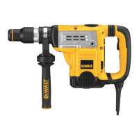
Fig. B
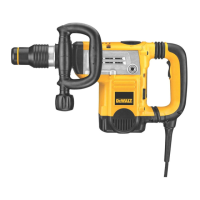
SHOCKS Active Vibration Control® System
(Fig. A, F)
D25651, D25601, D25603, D25831,
D25851
For best vibration control, hold the tool with one hand
on the main handle
4
and the other hand on the side
handle
3
. Apply just enough pressure so the damping
device on the main handle is approximately mid stroke. The
hammer only needs enough pressure to engage the active
vibration control. Applying too much pressure will not make
the tool drill or chip faster and active vibration control will
notengage.
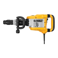
Inserting and Removing Spline Drive
Accessories (Fig. C)
D25553, D25651, D25851
WARNING: Burn hazard. ALWAYS wear gloves when
changing bits. Accessible metal parts on the tool and
bits may get extremely hot during operation. Small
bits of broken material may damage barehands.
WARNING: Do not attempt to tighten or loosen drill
bits (or any other accessory) by gripping the front part
of the chuck and turning the tool on. Damage to the
chuck and personal injury mayoccur.
1. Insert the bit shank into the tool holder
13
as far as
it will go. The groove on the chisel shank
17
must
be aligned with the symbol
15
on the toolholder. If
inserted correctly, the locking sleeve
16
moves back to
the end position and shows a closed locksymbol.
2. Pull on the bit to be sure that it is properlylocked.
3. If the chisel groove is not aligned with the symbol, or
is not inserted to the complete depth the lock symbol
remainsopen.
4. To remove the bit, pull back the locking sleeve and pull
the bitout.
Fig. C
13
17
15
16
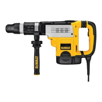
Inserting and Removing SDS Max
Accessories (Fig. D)
D25501, D25601, D25603, D25831
1. Pull back the locking sleeve
16
and insert the bit shank.
The bit shank must beclean.
2. Turn the bit slightly until the sleeve snaps back
intoposition.
3. Ensure the bit is properlyengaged.
NOTE: The bit needs to move several centimeters in and
out of the tool holder
13
when properlyengaged.
4. To remove the bit, pull back the locking sleeve and pull
the bitout.
 Loading...