11
ENGLISH
ENGLISH
Read instruction manual beforeuse.
Wear earprotection.
Wear eyeprotection.
Visible radiation. Do not stare intolight.
Date Code Position
The date code, which also includes the year of manufacture, is
printed into thehousing.
Example:
2017 XX XX
Year of Manufacture
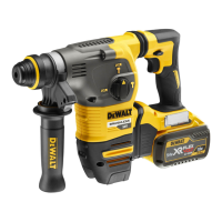
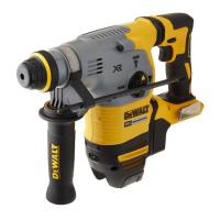
Description (Fig. A)
WARNING: Never modify the power tool or any part of it.
Damage or personal injury couldresult.
8
Main handle
9
SDS-Plus tool holder
10
Sleeve
11
Depth rod
12
Depth rod release button
13
Worklight
14
Utility hook
Intended Use
Your cordless rotary hammerdrill has been designed for
professional drilling and hammerdrilling applications, as well as
screwdriving and chippingapplications.
DO NOT use under wet conditions or in the presence of
flammable liquids orgases.
Your cordless rotary hammerdrill is a professional powertool.
DO NOT let children come into contact with the tool.
Supervision is required when inexperienced operators use
thistool.
• Young children and the infirm. This appliance is not
intended for use by young children or infirm persons
withoutsupervision.
• This product is not intended for use by persons (including
children) suffering from diminished physical, sensory or
mental abilities; lack of experience, knowledge or skills
unless they are supervised by a person responsible for their
safety. Children should never be left alone with thisproduct.
Overload Clutch
In case of jamming of a drill bit, the drive to the drill spindle is
interrupted. Because of the resulting forces, always hold the
tool with both hands and take a firmstance. After the overload,
release and depress the trigger to re-engagedrive.
Mechanical Clutch
These tools are fitted with a mechanical clutch. The indication
that the clutch has activated will be an audible ratcheting
together with increasedvibration.
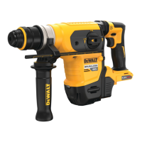
Anti-Rotation System (Fig. E)
In addition to the clutch, an anti-rotation system offers increased
user comfort and safety through an on-board, anti-rotation
technology capable of detecting if the user loses control of
thehammer. When a jam is detected, the torque and speed are
reducedinstantly. This feature prevents self rotation of the tool
reducing the occurrence of wristinjuries.
The anti-rotation system indicator
18
will illuminate to
indicatestatus.
Indicator Diagnosis Solution
OFF Tool is functioning
normally
Follow all warnings and instructions
when operating the tool.
SOLID Anti-Rotation
System has
been activated
(ENGAGED)
With the tool properly supported,
release trigger. The tool will function
normally when the trigger is depressed
again and the indicator light will go out
Active Vibration Control
For best vibration control, hold the tool as described in Proper
HandPosition.
The active vibration control neutralises rebound vibration from
the hammer mechanism. Lowering hand and arm vibration,
it allows more comfortable use for longer periods of time and
extends the life of theunit.
The hammer only needs enough pressure to engage the active
vibraton control. Applying too much pressure will not make
the tool drill or chip faster and active vibration control will
notengage.
ASSEMBLY AND ADJUSTMENTS
WARNING: To reduce the risk of serious personal
injury, turn tool off and disconnect battery pack
before making any adjustments or removing/
installing attachments/accessories or when making
repair. An accidental start-up can causeinjury.
WARNING: Use only
battery packs andchargers.
Inserting and Removing the Battery Pack
from the Tool (Fig. B)
NOTE: Make sure your battery pack
6
is fullycharged.
To Install the Battery Pack into the
Tool Handle
1. Align the battery pack
6
with the rails inside the tool’s
handle (Fig. B).
2. Slide it into the handle until the battery pack is firmly seated
in the tool and ensure that you hear the lock snap intoplace.
To Remove the Battery Pack from the Tool
1. Press the release button
7
and firmly pull the battery pack
out of the toolhandle.
2. Insert battery pack into the charger as described in the
charger section of thismanual.
Fuel Gauge Battery Packs
Some
battery packs include a fuel gauge which
consists of three green LED lights that indicate the level of
charge remaining in the batterypack.
To actuate the fuel gauge, press and hold the fuel gauge
button
19
. A combination of the three green LED lights will
illuminate designating the level of charge left. When the level
of charge in the battery is below the usable limit, the fuel gauge
will not illuminate and the battery will need to berecharged.
NOTE: The fuel gauge is only an indication of the charge left on
the battery pack. It does not indicate tool functionality and is
subject to variation based on product components, temperature
and end-userapplication.
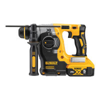
Side Handle (Fig. A)
WARNING: To reduce the risk of personal injury, ALWAYS
operate the tool with the side handle properly installed.
Failure to do so may result in the side handle slipping
during tool operation and subsequent loss of control. Hold
tool with both hands to maximizecontrol.
The side handle
5
clamps to the front of the gear case and
may be rotated 360˚ to permit right- or left-hand use. The side
handle must be tightened sufficiently to resist the twisting
action of the tool if the accessory binds or stalls. Be sure to grip
the side handle at the far end to control the tool during astall.
To loosen side handle, rotatecounterclockwise.
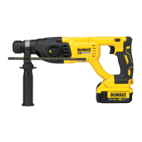
To Adjust the Depth Rod (Fig. C)
1. Push in and hold the depth rod release button
12
on the
sidehandle.
2. Move the depth rod
11
so the distance between the
end of the rod and the end of the bit equals the desired
drillingdepth.
3. Release the button to lock rod into position. When drilling
with the depth rod, stop when end of rod reaches surface
ofmaterial.
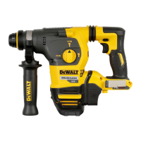
Utility Hook (Fig. A, D)
A utility hook
14
is fitted below the main handle
8
on the left
side of the tool. To extend the utility hook pull it out from the
side of the tool. To store the utility hook push it back flush with
the side of thetool. If use of the hook is not desired at all, it can
be removedcompletely.
To Remove and/or Reinstall the
Utility Hook
1. Position the utility hook into the extended position and
remove the hex head screw located on the underside of the
mainhandle.
2. Pull out the utility hook until it is free from theunit.
 Loading...