ENGLISH
8
OPERATION
WARNING: To reduce the risk of serious personal injury, turn unit off and disconnect
it from power source before making any adjustments or removing/installing
attachments or accessories. An accidental start-up can causeinjury.
The riving knife provided with this saw is marked as follows:
.063” (1.6mm) THICK RIVING KNIFE. ONLY FOR USE WITH 8-1/4” (210mm) BLADE WITH .071”
(1.8mm) MIN KERF WIDTH AND .055” (1.4mm) MAX BODYTHICKNESS.
Blade body thickness and kerf width dimensions for all
table saw blades are available at
www.dewalt.com
If a different blade is used and the body thickness and kerf width dimensions are not provided,
use the following procedure to determine the correct riving knife thickness:
1. Measure the body thickness of theblade.
2. Make a shallow cut in scrap material and measure the kerfwidth.
3. Select the riving knife
21
.
4. Slide the riving knife through the shallow cut made in step 2 to confirm the correct riving
knife has been selected. The riving knife should not bind or drag through thecut.
WARNING: If any dragging or binding of the material is encountered as it reaches the riving
knife, turn unit off and disconnect machine from power source. Repeat steps 1–4 to make the
proper riving knife selection before attempting anothercut.
Kickback
Kickback is a dangerous condition! It is caused by the workpiece binding against the blade. The
result is that the workpiece can move rapidly in a direction opposite to the feed direction. During
kickback, the workpiece could be thrown back at the operator. It can also drag the operator’s
hand back into the blade if the operator’s hand is at the rear of the blade. If kickback occurs, turn
the saw OFF and verify the proper functioning of the riving knife, anti-kickback assembly and
blade guard assembly before resumingwork.
WARNING: See Additional Safety Rules for Table Saws and follow all warnings
provided regardingKICKBACK.
WARNING: Before using the saw, verify the following each and every time:
• ALWAYS wear proper eye, hearing and respiratoryequipment.
• Blade is securelytightened.
• Bevel angle and rail lock levers arelocked.
• If ripping, ensure that rip fence locked lever is locked and that the fence is parallel to
theblade.
• If crosscutting, miter gauge knob is securelytightened.
• The blade guard assembly is properly attached and the anti-kickback assembly
isfunctioning.
• ALWAYS inspect the blade guard assembly and riving knife for proper alignment,
operation and clearance with sawblade.
• ALWAYS make sure both guards are in the down position in contact with the table
beforeoperating.
WARNING: To reduce the risk of serious personal injury, have push stick ready to use before
startingcut.
Failure to adhere to these common safety rules can greatly increase the likelihood ofinjury.
WARNING: Before connecting the table saw to the power source or operating the saw,
always inspect the blade guard assembly and riving knife for proper operation alignment
and clearance with saw blade. Personal injury may result.
WARNING: Ripping or crosscutting may cause saw to tip over while operating. Make sure
saw is securely mounted to a stablesurface.
WARNING: Never use the fence and miter gauge together. This may cause a kickback
condition and injure theoperator.
CAUTION: If this saw makes an unfamiliar noise or if it vibrates excessively, cease operating
immediately, turn unit off and disconnect from power source until the problem has been
located and corrected. Contact a
factory service center, a
authorized
service center or other qualified service personnel if the problem cannot be found.
WARNING: The proper throat plate must be in place at all times to reduce the risk of a
thrown workpiece and possibleinjury.
There are two basic types of cutting with table saws: ripping and crosscutting. Regardless of
material, man made or natural wood, the distinction between ripping and crosscutting is as
follows: Ripping is cutting to a different width (usually with the grain) and crosscutting describes
cutting material across the shorter dimension (usually against the grain).
WARNING: When ripping, always use the fence to provide a guide for the material and blade
guard assembly to protect against a kickbacksituation.
WARNING: Never perform any cutting operation freehand. Never perform plungecutting.
WARNING: When crosscutting, always use the miter gauge. Do not use both the rip fence
and miter gaugetogether.
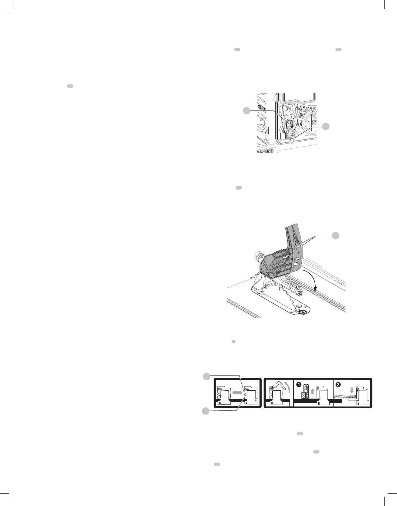
ON/OFF Switch (Fig.O)
WARNING: To reduce the risk of injury, be sure the switch is in the OFF position before
plugging machine in.
Push green button
44
in to turn this saw on and push down the red paddle
46
to turn this
sawoff.
Lock Off Feature Instructions
A cover above the switch folds down for insertion of a padlock to lock the saw off. A padlock
with a maximum diameter of 1/4"(6.35mm) and minimum clearance of 3" (76.2 mm) is
recommended.
44
46
Fig. O
Guard Operating Feature (Fig.P)
WARNING: To reduce the risk of serious personal injury, turn unit off and disconnect
it from power source before making any adjustments or removing/installing
attachments oraccessories. An accidental start-up can causeinjury.
1. The guard arms
48
will lock in place when in the raisedposition.
2. This feature improves visibility when measuring the blade to fencedistance.
3. Push down on guard(s) and they will release to the operatingposition.
NOTE: Pull on the anti-kickback assembly to ensure it is locked inplace.
ALWAYS make sure both guards are in the down position in contact with the table
beforeoperating.
Fig. P
48
Rip Fence Operation (Fig. A,Q)
Rail Lock Lever (Fig. A)
The rail lock lever
5
locks the fence in place preventing movement during cutting. To lock the
rail lever, push it down and toward the rear of the saw. To unlock, pull it up and toward the
front of thesaw.
WARNING: When ripping, always lock the rail locklever.
Fig. Q
50
49
Work Support Extension/Narrow Ripping Fence (Fig. A, Q)
The table saw is equipped with a narrow ripping fence
18
that also supports work that extends
beyond the sawtable.
To use the narrow ripping fence in the work support position, rotate it from its stored position as
shown in Figure Q, and slide the pins into the lower sets of slots
49
on both ends of thefence.
To use the narrow ripping fence in the narrow ripping position, snap the pins into the upper sets
of slots
50
on both ends of thefence.
This feature will allow 2" (51mm) of extra clearance to the blade. Refer to FigureT.
NOTE: When not in use, the narrow ripping fence should be placed in its storedposition.
 Loading...