ExpressCard SD
Power Ready Diagnostic
Console Modem
DTR
DCD
Factory Reset
USB1
USB2
XBee
C O N N E C T P O R T
LTS
Quick Start Guide
1
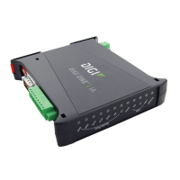
ConnectPort LTS
RJ-45 diagnostic loopback
Power cord (US models only)
What’s in the box
© 2015 Digi International Inc. Digi, Digi International Inc., ConnectPort, RealPort, and the Digi logo are trademarks or registered trademarks of Digi International Inc. in the United States and other countries worldwide. All other trademarks are the property of
their respective owners.
ConnectPort® LTS 8/16/32
2
Connect the hardware
Connect the Ethernet cable to the Ethernet 1 port.
Connect the serial devices to the serial ports, following the pin-position
information below. If serial devices are EIA-422/485, see steps 4e and 4f.
b
Cord and brick power
supply (for LTS 8 models).
Power cord
(for U.S.
models).
Connect the power supply to the POWER connector.
ConnectPort LTS
Cord and brick power supply
(ConnectPort LTS 8 models only)
Pin # on
10-wire
connector
EIA-422/485
Full-Duplex
EIA-232
1 RI TxD-
2 DSR* RxD-
3 RTS RTS+
4 CGND CGND
5 TxD TxD+
6 RxD+
7 SGND SGND
8 CTS CTS+
9 DTR RTS-
10 CTS-
RxD
DCD*
EIA-485
Half-Duplex
N/A
DATA-
N/A
CGND
N/A
DATA+
SGND
N/A
N/A
N/A
Serial port pin assignments:
MEI versions only:
ConnectPort LTS
products use an
RJ-45 10-wire jack
(female), with Pin 1
in the following
location:
a
Pin # on
8-wire
connector
2
3
4
5
6
7
8
1
10-wire connector
(male):
Pin positions for connecting serial devices:
For an 8-wire
connector,
connect the pins
to the center 8 pins
of the 10-wire jack:
For a 10-wire
connector, Pin 1
of the connector is
in the following
location:
10-wire jack
(female):
8-wire connector
(male):
Ports, connectors, LEDs, and buttons:
Insertion
end
Insertion
end
Pin 1
c
*Use the Altpin setting to swap these two signals.
DP-9F console adapter
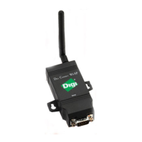
XBee antenna
(W models only)
Rack mount brackets
(16/32 port models only)
Ethernet cable
W models only: Connect the XBee antenna to the XBEE connector.
d
Serial port side
Reverse side
a
b
c
d
Top
view
Top
view
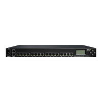
ConnectPort LTS 16/32 - Serial port side
ConnectPort LTS 16/32 - Reverse side
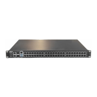
ConnectPort LTS 16 Dual Power - Serial port side
ConnectPort LTS 16 Dual Power - Reverse side
C
O N N E C T
P
O R T
L T S 3 2
Up
Dn
Sel
Ext
1 2 3 4 5 6 7 8
17 18 19 20 21 22 23 24
9 10 11 12 13 14 15 16
25 26 27 28 29 30 31 32
Ethernet 1
Ethernet 2
Power
SD
USB1
USB2
C
O N N E C T
P
O R T
L T S 8
Power Ready Diagnostic
XBee
Up
Dn
Sel
Ext
C
O N N E C T
P
O R T
L T S 1 6
1 2 3 4 5 6 7 8 9 10 11 12 13 14 15 16
Ethernet 1
Ethernet 2
Power 2
Power 1
SD
Power 1 Power 2 Ready Diagnostic
Console Factory Reset
C O N N E C T P O R T
LTS
Up
Dn
Sel
Ext
Power
–
+
C
O N N E C T
P
O R T
LTS-W
Console
Modem
DTR
DCD
Factory
Reset
Ethernet 1
Ethernet 2
1 2 3 4
5 6 7 8
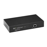
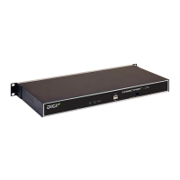
ConnectPort LTS 8 - Serial port side
Power
connector
Ethernet
ports
Serial ports
Analog
modem
port (W
models only)
DTR/
DCD
LEDs
Factory
reset
button
Console
port
Power
connector
Ethernet
ports
Serial ports
LCD
display
LCD
control
buttons
Express
card slot
(W models
only)
SD card
slot
Power
LED
Ready
LED
Diagnostic
LED
XBee
antenna
connector
(W models
only)
USB
ports
Factory
reset
button
Console
port
DTR/
DCD
LEDs
Analog
modem
port (W
models
only)
Serial ports
Ethernet
ports
Power 2
connector
Power 1
connector
Console
port
Factory
reset
button
Power 1
LED
Power 2
LED
Ready
LED
SD card
slot
Diagnostic
LED
LCD
display
LCD
control
buttons
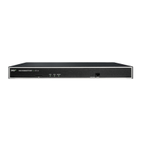
ConnectPort LTS 8 - Reverse side
SD
USB1
USB2
C
O N N E C T
P
O R T
L T S 8
Power Ready Diagnostic
XBee
Up
Dn
Sel
Ext
Diagnostic
LED
SD card
slot
USB
ports
XBee
antenna
connector
(W models
only)
Power
LED
Ready
LED
LCD
display
LCD
control
buttons