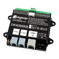
DR4088RB
www.digikeijs.com P 5
Connecon
The DR4088RB is connected to the R-Bus on the respecve control unit as described in the control unit manual.
The DR4088RB has 16 (!) feedback inputs. The DR4088RB can thus replace two Roco 10787 feedback modules.
However, the DR4088RB can also be congured to only use only the rst 8 inputs. In addion, the DR4088RB
can be expanded with the standard DR4088 s88 modules. For this, the DR4088RB must be congured in order
to use up to a maximum of 80 inputs.
The ROCO R-bus is divided into two groups: group 0 and group 1. Group 1 includes module numbers from 1 to
10 and group 1 from 11 to 20. Fully using Digikeijs DR4088 modules would mean two DR4088RB (1 for group 0
and 1 for group 1) and eight DR4088 s88 modules. This uses the enre feedback capacity (160 inputs) of the R-
Bus. If you have a Z21 (black), the Digikeijs DR4088LN connected to the L-Bus of the Z21 oers the possibility of
using up to 2048 inputs.
Conguraon
The DR4088RB can be congured with the Z21 maintenance program in the same way as the Roco 10787 modules. The
DR4088RB factory seng is module address 1 and 2 modules. If this is your rst module on the R-Bus you do not need to
congure anything. To connect further modules, follow this procedure:
1. Module address:
2. Connect only (!!!) the DR4088RB to the R-Bus. The green LED next to the programming buon blinks at a moderate
pace (on-o-on-o).
3. Follow the procedure to program modules as described for the Roco 10787. Enter the module address.
4. When the program asks you to connect the 10787 to the R-Bus, press the programming buon on the DR4088RB.
The green LED will blink slower (long-o, short-on, long-o, short-on etc.)
5. Connue with the procedure for assigning the module address. The control unit will now send addresses to the R
bus.
6. When the DR4088RB receives its module address, the LED will return to its inial blinking frequency: on-o-on-o-
on-o etc.
7. Finish the procedure for programming Roco 10787s.
If you have not connected a DR4088 s88 extension to the DR4088RB, the module is now ready for use.
1. Mulple modules (oponal, see above):
2. Connect only (!!!) the DR4088RB to the R-Bus. The green LED next to the programming buon blinks at a moderate
pace (on-o-on-o).
3. Follow the procedure to program modules as described for the Roco 10787.
4. When the program asks you to connect the 10787 to the R-Bus, press the programming buon on the DR4088RB.
The green LED will blink slower (long-o, short-on, long-o, short-on etc.)
5. Now press the buon again. The green LED will blink at the same rate, but with a dierent paern (long-on, short-
o, long-on, short-o etc.).
6. Now enter the number of modules instead of the number for the module address. This number is the number of
connected inputs divided by two. For example, only one DR4088RB -> 2; 1 DR4088RB + 1 DR4088 s88 -> 4; 1
DR4088RB + 4 DR4088 s88 -> 10.
7. Connue the procedure for assigning the module address. The control unit now sends the number of modules to
the R-Bus.
8. When the DR4088RB has received the number of modules, the LED will return to its inial blinking frequency: on-o
-on-o-on-o etc.
9. Finish the procedure for programming Roco 10787s.
 Loading...