DOIT.AM
®
User Manual for TTL-WiFi DT-06
Shenzhen Doctors of Intelligence & Technology Co., LTD (www.doit.am) Copyright@2014-2017
Page 6
LED
SW2 SW1
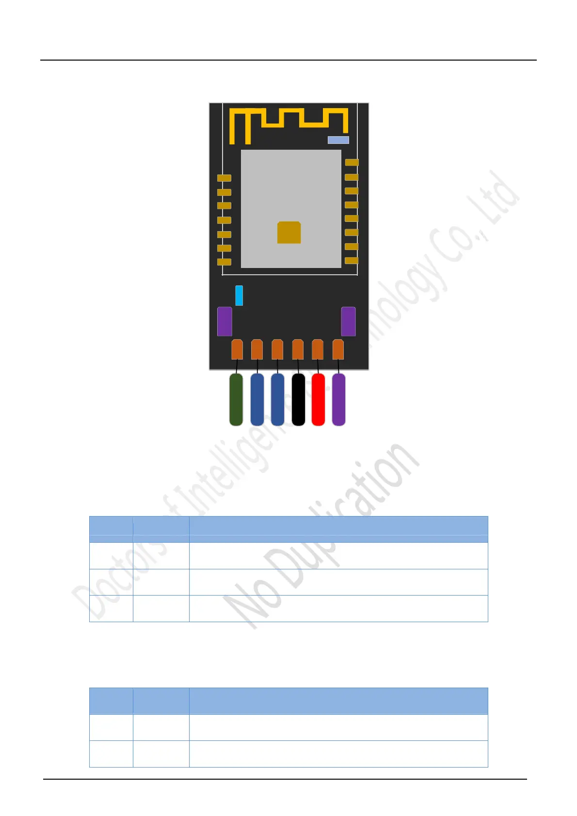
1 2 3 4 5 6
STATE
RXD
8
1
0
9
1
1
1
2
1
3
1
4
ESP‐M2
1
5
16
1 2 43 5 6 7
TXD
GND
VCC
EN
TTL‐WiFi
Fig. 2.1 TTL-WiFi Interface definition
Functions of button and LED
Table 2.1 Functions of button and LED
Num. Type Function illustration
1 LED
LED connected to VCC3.3
y a pull up resitance, and other is
connected to GPIO4
2 SW1
Connected to GPIO0 to coordinate with SW2
utton to download
the firmware.
3
SW2
Connect to RST, to coordinate with SW1 to download the firmware
Importantly, when downloaded the firmware, please firstly press SW1 button, and then press SW2
button, and at last loose the button to finish the download. (Refer to the ESP-M2 module)
Table 2.2 LED definition
Num
LED
indicator
Function
1
Always
lighting
Successfully connect to the wireless router when WiFi module is a
STA or STA+AP mode
2
Lighting
slowly
Level for IO switches once each 1s; if works at AP mode, it shows tha
the WiFi module unsuccessfully connected to the wireless WiFi router;
 Loading...