INSTALLATION
TOOLS
• Flathead Screwdriver (for wire terminals)
• Philips Screwdriver (for mounting screws)
ACCESSING SETTINGS
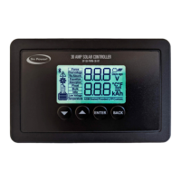
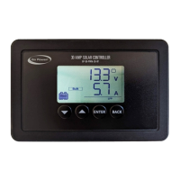
VIEWING CONTROLLER DISPLAY
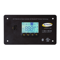
The GP-SB-PWM-30BT includes an LCD of FSTN type with 4 mechanical buttons
that act as navigation keys to control the display. The GP-
SB-PWM-30BT settings
can be accessed by entering menu number 2 as shown below.
BLUETOOTH
®
FEATURE
A Bluetooth® Low Energy module is integrated in the 30A model only.
For details on the data that can accessible/managed via Bluetooth®, please refer to
the GP-SB-PWM-10/30BT User Manual.
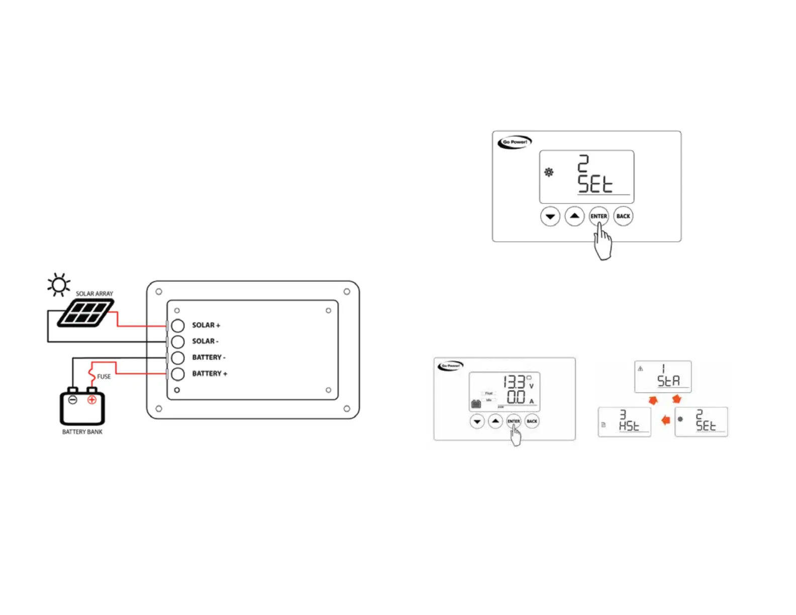
Three menus are implemented in the display: status, settings, and history. At power
up, the controller turns on within the status menu. The different menus can then be
accessed by pressing the Enter key as shown below.
INSTALLATION STEPS:
Install your solar array, and cover with opaque material until all wiring is complete.
Wiring should not exceed 25ft from the solar panels to the battery.
Wire the GP-SB-PWM-30BT according to the wiring diagram below. Be sure to torque
all screws based on the wire gauge after installation, as well as after 30-days.
The GP-SB-PWM-30BT is designed to be mounted flush against a wall, out of the way
but easily visible.
The GP-SB-PWM-30BT should be:
• Mounted as close to the battery bank as possible
• Mounted on a vertical surface to optimize cooling of the unit
• Indoors, protected from the weather
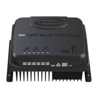
30 AMP SOLAR CONTROLLER
GP-SB-PWM-30-BT
30 AMP SOLAR CONTROLLER
GP-SB-PWM-30-BT
 Loading...