user’s manual TEC 30
25
GB
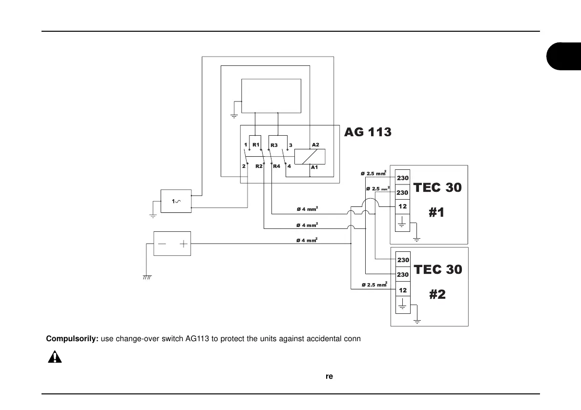
WIRING DIAGRAM - 2 TEC30 IN PARALLEL MODE
#2
TEC 30
TEC 30
#1
230
AG 113
3
R3
A2
R4 4
A1
230
230
230
12
R1
1
2 R2
12
Ø 2.5 mm
2
Ø4mm
2
Ø4mm
2
Ø4mm
2
Ø 2.5 mm
2
Ø 2.5
mm
2
Compulsorily: use change-over switch AG113 to protect the units against accidental connection to the main electric line
WARNING!
All generators connected to the wiring system must be on off position before executing any maintenance operation!
LOAD
MAINS
BATTERY
For parallel connection of 2 TEC30
follow the diagram in the picture .
(Accessory sold upon request)
 Loading...