Dräger Medical AG & Co. KGaA 6173.3
All rights reserved. Copyright reserved.
_ _Printed on_18.05.05_F61733XXT01.fm
45
Function description Babylog 8000
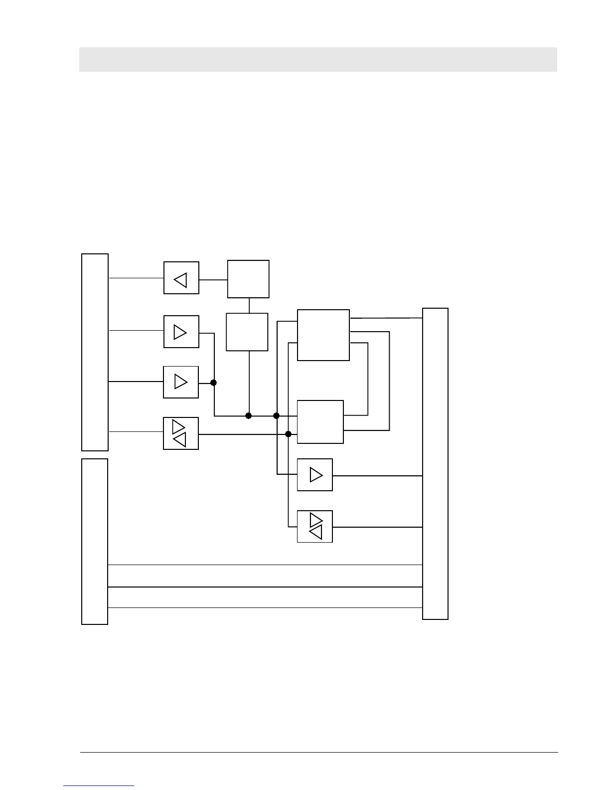
10.7 Front Adapter PCB
The Front Adapter PCB connects the CPU 68000 to the front panel. The front panels provides the control
and display elements.
The Front Adapter PCB reduces the 16-bit data bus to 8 bits, generates control signals for the front panel,
and controls the LC display (VIDEO RAM and LCD controller) or the EL display.
The power supply and the analog signals are led from the Motherboard PCB to the front panel through the
Front Adapter PCB.
Fig. 21: Block diagram of the Front Adapter PCB
Digital bus 68000
DTACKQ
Control bus
Adress bus
Data bus
DTACK
generator
Adress
decoder
LCD-
Controller
Dual-
Port-
RAM
Daten-Bus (16 bit)
seriell Datas to LC display
Frontcontroller
Adress and Control bus
Data bus (8 bit)
I/O connections
Ansteuerung Alarm LED
analog current power
Potentiometer monitoring
 Loading...