Eaton Corporation
Electrical Sector
1111 Superior Ave.
Cleveland, OH 44114
United States
877-ETN-CARE (877-386-2273)
Eaton.com
© 2011 Eaton Corporation
All Rights Reserved
Printed in USA
Publication No. IL04707001E / Z11206
June 2011
Eaton is a registered trademark
of Eaton Corporation.
All other trademarks are property
of their respective owners.
Instructional Lea et IL04707001E
Effective June 2011
10250T contact block assembly
Push–pull operators
Application guide
To assist in the selection of contact blocks, the diagram on page 1
shows pictorially by symbols “A” and “B” locations of contact
circuits after assembly of contact blocks to the operator. Table 1 and
Table 2 show the effect of the push and pull operations on either
NO or NC contacts.
A maximum of two contact blocks may be used with each operator.
Maximum torque of stacking screws is 9 in-lbs. Adding more
than two blocks may cause this switch to malfunction. Single
circuit contact must be mounted under circuit “A”. Special function
contact blocks are not available for use with the three-position
push–pull operator.
ote: N Buttons and lenses in various colors are ordered and packaged sepa-
rately. This pushbutton unit is oiltight when the adapter gasket and button or
lens gasket are securely tightened.
Table 1. Push–Pull Operator Types
Operator
Type
Contact
Block
Circuit
Operator Mode and Contact Circuit
Pulled Intermediate Pushed
Circuits
A B
Circuits
A B
Circuits
A B
Momentary
push and pull
and
momentary pull,
maintained push
2NC
1NO
X X
O
O X
O
O O
X
Maintained
push and pull
(Two-positions)
1NC
2NC
1NO
2NO
X or X
X X
O or O
O O
No
intermediate
position
O or O
O O
O O
X X
Momentary
push and pull
(Three-positions)
1NO–1NC O X O O X O
ote: N X = contacts closed; O = contacts open
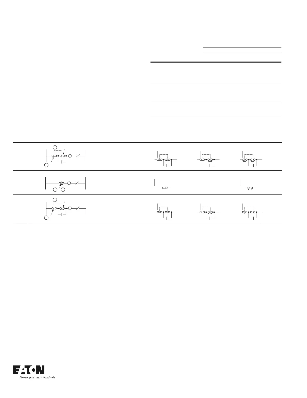
Table 2. Push–Pull Wire Position Operation
Control Line Diagram Operator Circuits Operator Mode
Three-wire,
three-position,
momentary
Circuit
Circuit
L2L1
M
M
OL
A
B
Momentary
push and pull
2NC
contact
blocks
START
(Momentary)
Normal position
(Maintained)
STOP
(Momentary)
Two-wire,
two-position,
maintained
Circuit
L2L1
M
or
OL
A
B
Maintained
push and pull
1NC
contact
blocks
START
(Maintained)
No
intermediate
position
STOP
(Maintained)
Three-wire
momentary pull,
maintained push
Circuit
Circuit
L2L1
M
M
OL
A
B
Maintained
push and
maintained
ready,
momentary
pull to start
2NC
contact
blocks
START
(Momentary)
Normal position
(Maintained)
STOP
(Momentary)
 Loading...