P50796 Rev 07 P50796 Rev 07
Effective: June 2010 Effective: June 2010
INSTRUCTION MANUAL:
ENHANCED 50 SERIES PHOTOELECTRIC SENSORS
THRU-BEAM
MODELS COVERED IN THIS MANUAL
AC/DC Models
Style Output Type
6-Foot Cable
Integral Micro Quick
Disconnect Integral Mini Quick Disconnect
Pigtail Micro
Quick Disconnect
No Time
Delay
With Time
Delay
No Time
Delay
With Time
Delay
No Time
Delay
With Time
Delay
No Time
Delay
With Time
Delay
200-Foot Thru-Beam
Source (Emitter)
N/A 1150E-6513 N/A 1150E-6543 N/A 1150E-6504 N/A 1150E-6534 N/A
200-Foot Thru-Beam
Detector (Receiver)
Solid-State Relay 1250E-6513 1250E-8513 1250E-6543* 1250E-8543* 1250E-6503 1250E-8503 1250E-6533 1250E-8533
Electromechanical
Relay
1250E-6514 1250E-8514 N/A N/A 1250E-6504 1250E-8504 1250E-6534 1250E-8534
500-Foot Thru-Beam
Source (Emitter)
N/A 1151E-6513 N/A 1151E-6543 N/A 1151E-6504 N/A 1151E-6534 N/A
500-Foot Thru-Beam
Detector (Receiver)
Solid-State Relay 1251E-6513 1251E-8513 1251E-6543* 1251E-8543* 1251E-6503 1251E-8503 1251E-6533 1251E-8533
Electromechanical
Relay
1251E-6514 1251E-8514 N/A N/A 1251E-6504 1251E-8504 1251E-6534 1251E-8534
DC Models
Style
Emitter LED Output Type
6-Foot Cable
Integral Euro (Micro) Quick
Disconnect Integral Mini Quick Disconnect
Pigtail Euro (Micro) Quick
Disconnect
No Time
Delay
With Time
Delay
No Time
Delay
With Time
Delay
No Time
Delay
With Time
Delay
No Time
Delay
With Time
Delay
200-Foot Thru-Beam
Source (Emitter)
N/A 1150E-6517 N/A 1150E-6547 N/A 1150E-6507 N/A 1150E-6537 N/A
200-Foot Thru-Beam
Detector (Receiver)
NPN/PNP 1250E-6517 1250E-8517 1250E-6547 1250E-8547 1250E-6507 1250E-8507 1250E-6537 1250E-8537
500-Foot Thru-Beam
Source (Emitter)
N/A 1151E-6517 N/A 1151E-6547 N/A 1151E-6507 N/A 1151E-6537 N/A
500-Foot Thru-Beam
Detector (Receiver)
NPN/PNP 1251E-6517 1251E-8517 1251E-6547 1251E-8547 1251E-6507 1251E-8507 1251E-6537 1251E-8537
* Versions of these sensors are available with a non-isolated output. Non-isolated output models end in -45, ex. 1350E-6545. For more information, consult wiring diagrams on Page 4.
WARNING
THESE PRODUCTS ARE NOT DESIGNED, TESTED, OR RECOMMENDED FOR
USE IN HUMAN SAFETY APPLICATIONS.
DURING INSTALLATION, CORRECT POWER CONNECTIONS MUST BE
MADE FIRST TO ENSURE FAIL-SAFE SHORT CIRCUIT PROTECTION OF THE
OUTPUTS. REFER TO THE WIRING DIAGRAMS IN THIS MANUAL.
DO NOT USE TOOLS TO APPLY TORQUE DIRECTLY TO SENSOR BODY.
ALIGN SENSOR BY HAND BEFORE TIGHTENING MOUNTING HARDWARE.
ADJUSTMENT POTS ARE 3/4 TURN DEVICES. ANY RESISTANCE
ENCOUNTERED WHILE ADJUSTING THESE POTS INDICATES YOU HAVE
REACHED THE ADJUSTMENT LIMIT STOP. TURNING PAST THIS STOP
WILL DAMAGE THE SENSOR.
USE ONLY THE ADJUSTMENT TOOL PROVIDED OR SUITABLE
SCREWDRIVER WHEN TURNING ADJUSTMENT POTS OR SETTING SWITCH
POSITIONS. SHARP OBJECTS CAN DAMAGE THE SENSOR AND RESULT IN
ELECTRICAL SHOCK.
ENSURE THE PRODUCT IS CONNECTED TO THE CORRECT POWER SUPPLY
FOR THE APPLICATION. REFER TO THE WIRING DIAGRAMS IN THIS
MANUAL.
AC/DC CONNECTOR VERSION SENSORS ARE EQUIPPED WITH AN AC-
TYPE CONNECTOR. THE USE OF DC POWER WITH AC-TYPE CONNECTORS
MAY NOT CONFORM WITH ESTABLISHED STANDARDS.
Page 1Page 4
INTRODUCTION
Enhanced 50 Series photoelectric sensors offer fl exibility, durability, and
high optical performance in a low-cost self-contained package. Each
sensor features several mounting options and a low-gain indicator for quick
installation and easy alignment. Models are available for operation with
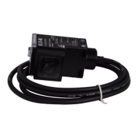
DC power, or AC and DC power in a single unit. Sensors are wired using a
6-foot power cable, body-mounted quick disconnect mini connector, body
mounted quick disconnect micro (AC/DC Micro or Euro (Micro)) connector, or
quick disconnect micro (AC/DC Micro or Euro (Micro)) connector on a short
cable pigtail. All sensors have built-in light/dark selection, and modes are
available with timing features that include on-delay, off-delay, and one-shot
delay.
An Enhanced 50 thru-beam photoelectric sensor installation consists of an
emitter and a receiver positioned on opposite sides of a detection zone. The
emitter emits infrared light, which is detected by the receiver. The receiver
output switches on when this beam of light is either blocked (when set in
dark operate mode) or completed (in light operate mode).
A complete system consists of an emitter and receiver mounted such that
the emitter directs its light beam at the receiver and the receiver is aimed
to detect the beam. The emitter and receiver can be separated by up to 61
meters (200 feet) using standard range models and 152 meters (500 feet)
using extended range models.
WIRING DIAGRAMS (Pin numbers are for reference only; rely on pin location when wiring)
Operating Voltage Models Cable Models Mini-Connector Models
(Face View Male Shown)
Micro-Connector Models
(Face View Male Shown)
10-40V DC Thru-Beam Emitters
Thru-Beam Receivers
12-240V DC or
24-240V AC with
Solid-State Relay
Thru-Beam Emitters
Thru-Beam Receivers
with Isolated AC/DC
Output
Thru-Beam
Receivers with
Non-Isolated AC/DC
Output
12-240V DC or
24-240V AC with
SPDT EM Relay
Thru-Beam Emitters
Thru-Beam Receivers
1
Connect load to the appropriate outlet for either sinking or sourcing operation.
2
Connecting the test input to 0V DC allows you to switch the light source off for troubleshooting while leaving the sensor under power.
3
Over current protection is to be provided in the fi eld. Conductor size for 20 AWG: 5 amp; 22 AWG: 3 amp; 24 AWG: 2 amp.
BU
BR
BK
Test In
(+)
(
–
) OV
Test In
(
–
)
OV
(+)
Test In
(
–
)
OV
(+)
BU
WH
NPN
PNP
(
–
)
OV
BK
BN
(+)
Load
Load
(+)
(
–
)
OV
PNP
NPN
Load
Load
(+)
(
–
)
OV
PNP
NPN
Load
Load
BU
BR
L1
(+)
L2
(
–
)
L2
(
–
)
L1
(+)
L1
(+)
L2
(
–)
BU
BK
WH
BR
L1
(+)
L2
(
–
)
Isolated
AC/DC Output
L2
(
–
)
L1
(+)
Isolated
AC/DC Output
L1
(+)
L2
(
–
)
Isolated
AC/DC
Output
L1
(
–
)
L2
(+)
Load
BU
BR
L1
(+)
L2
(
–
)
L2
(
–
)
L1
(+)
L1
(+)
L2
(
–)
BU
OR
BK
BR
WH
N.C.
COM
N.O.
–
L1
(+)
L1
(+)
COM
N.O. N.C.
L2
(
–
)
L1
(+)
L2
(
–
)
COM
N.O. N.C.