5
Instruction Leaet IL01301051E
effective September 2013
Operating Manual for Series NRX
Trip Units - Digitrip™ 520/520M
EATON www.eaton.com
List of Figures
page
List of Tables
page
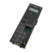
Figure 1. Example Digitrip 520M LSIG with legend ............7
Figure 2. Digitrip Nameplates ............................10
Figure 3. Installation of the Trip Unit into Frame Module
of a Series NRX Circuit Breaker ..........................11
Figure 4. Installation of the Rating Plug into the Trip Unit .......11
Figure 5. Block Diagram with Breaker Interface ..............13
Figure 6. Applying Long Delay Settings ....................15
Figure 7. Long Delay Current Settings ......................15
Figure 8. Long Delay Time Settings ........................15
Figure 9. Long Time Memory (LTM) Jumper .................15
Figure 10. Applying Short Delay Settings ...................16
Figure 11. Short Delay Current Settings ....................16
Figure 12. Short Delay Time Settings ......................16
Figure 13. Applying Instantaneous Settings .................16
Figure 14. Instantaneous Settings .........................16
Figure 15. Applying Ground Fault Settings ..................17
Figure 16. Ground Fault Current Settings ...................17
Figure 17. Ground Fault Time Settings ......................17
Figure 18. Sensor Types ................................20
Figure 19. Functional Test Kit .............................21
Figure 20. Digitrip Battery Installation ......................22
Figure 21. Digitrip 520M in Maintenance Mode ..............25
Figure 22. Communication Module ........................26
Figure 23. Curve Select .................................26
Figure 24. Typical Zone Interlocking ........................27
Figure 25. Typical Zone Interlocking Connections with two
Main Circuit Breakers (M1, M2) and a Tie Circuit Breaker (T) ....28
Figure 26. Connection Details for Conducting Single-Pole,
Single-Phase Current Tests With the Circuit Breaker
Removed From the Cell .................................31
Figure 27. Connection Details for Conducting Single-Phase Current
Tests With the Circuit Breaker Removed From the Cell ........32
Figure 28. Typical Trip Function Record Nameplate ............33
Figure 29. Automatic Trip Operation Record .................33
Figure 30. Typical Performance Test Record Form .............34
Figure 31.
Series NRX-NF frame (IZMX16/IZM91) breaker master
connection diagram drawing number 6D32389 ..............35
Figure 32. Series NRX-NF frame (IZMX16/IZM91) breaker master
connection diagram drawing number 6D32389 ..............36
Figure 33. Series NRX-RF frame (IZMX40/IZM95) breaker master
connection diagram drawing number 6D32424 ..............37
Figure 34. Series NRX-RF frame (IZMX40/IZM95) master connection
diagram drawing number 6D32424 ........................38
Table 1. Catalog Number References .......................6
Table 2. Legend for Figure 1 ..............................7
Table 3. Available Digitrip 520 and 520M Trip Units ............8
Table 4. Technical Data ..................................9
Table 5. Series NRX/Digitrip Ground Fault Sensing Modes .....18
Table 6. Ground (Earth) Fault Current Settings Source
Ground/Zero Ground Fault Settings ........................18
Table 7. Ground (Earth) Fault Current Setting - Residual
NF Frame (IZMX16/IZM91) ..............................18
Table 8. Ground (Earth) Fault Current Setting - Residual
RF Frame (IZMX40/IZM95) ..............................19
Table 9. NRX Type NF Frame Rating Plugs ..................23
Table 10. NRX Type RF Frame Rating Plugs .................24
 Loading...
