EATON Diesel Plus O & M Manual IM05805019K
Diesel Engine Fire Pump Controller Effective June 2011
EATON CORPORATION www.ceaton.com 15
6.3 Controller Diagnostics
The Diesel Plus controller has a number of diagnostic points
that can be used to help in troubleshooting issues with the
controller. The diagnostics can be viewed on the main display,
saved to a USB storage device, or viewed on the optional
embedded webpage.
In order to view the diagnostics on the display press the up or
down arrow buttons from the main screen until the display
shows “Controller Diagnostics”. Press the Ack. Alarm button to
view the diagnostics. The display will show the diagnostics. In
order to navigate the diagnostics use the up or down arrow
buttons.
NOTE
The diagnostic information shall be provided to personnel trained in the
meaning of the values shown.
Diagnostic values that are recorded are the current date and
time, the microprocessor’s firmware version, Eaton’s shop
order number, customer order number, voltage readings,
pressure sensor readings, input status, and relay status.
Refer to Section 7 to save the controller diagnostics to a USB
storage device or to view the message history on the optional
embedded webpage.
7. COMMUNICATION
The Diesel Plus controller is available with a number of optional
communication protocols that can be used for the collection of
information.
Communication protocols include USB (standard), Ethernet and
RS485 (both optional).
7.1 USB
The USB port is used to download the controller message
history, statistics, diagnostics, status and configuration data to
a USB storage device. The USB port can also be used to upload
custom messages, additional languages, and update the
microprocessor firmware.
7.1.1 Information Download
• In order to download the history, diagnostics, statistics,
status and configuration - install a USB storage device into
the USB port on the display board. With the power on, press
the Data | Print button. The first selection is “Save to USB”.
Press the Ack. Alarm button and the controller will save the
information to the USB storage device.
• There will be five (5) files saved to the storage device. Refer to
Table 6 for the file nomenclature.
• The .csv file is a comma separated values file that can be
opened using standard spreadsheet, word processor, or
database programs. The .txt files can be opened using
standard text viewers.
7.1.2 Custom Message Upload
• The Diesel Plus controller has the ability to store and use up
to ten (10) custom messages that can appear based on a
specific date, time, alarm or status condition.
• Refer to Appendix H to upload and enable the custom
messages.
• Refer to Section 8 for the creation of the custom message file.
7.1.3 Firmware Update
• Contact the factory or an authorized trained representative for
assistance.
7.1.4 Language Upload
• Contact the factory or an authorized trained representative for
assistance.
7.2 Embedded Webpage (Optional)
The controller is available with an optional webpage that can be
used to view the main display of the controller and its current
status.
Contact the factory or an authorized trained representative for
assistance in accessing the webpage.
7.3 RS485 Serial Port (Optional)
Contact the factory or an authorized trained representative for
assistance.
7.4 RS232 Serial Port (Optional)
This port is used with the optional printer (X1) to initiate a print
cycle.
Last High Engine Temp. Date & Time
Last Overspeed Date & Time
Last Fail To Start Date & Time
Last Low Fuel Date & Time
Last Charger Failure Date & Time
Last Battery Failure Date & Time
Last ECM Alarm Date & Time
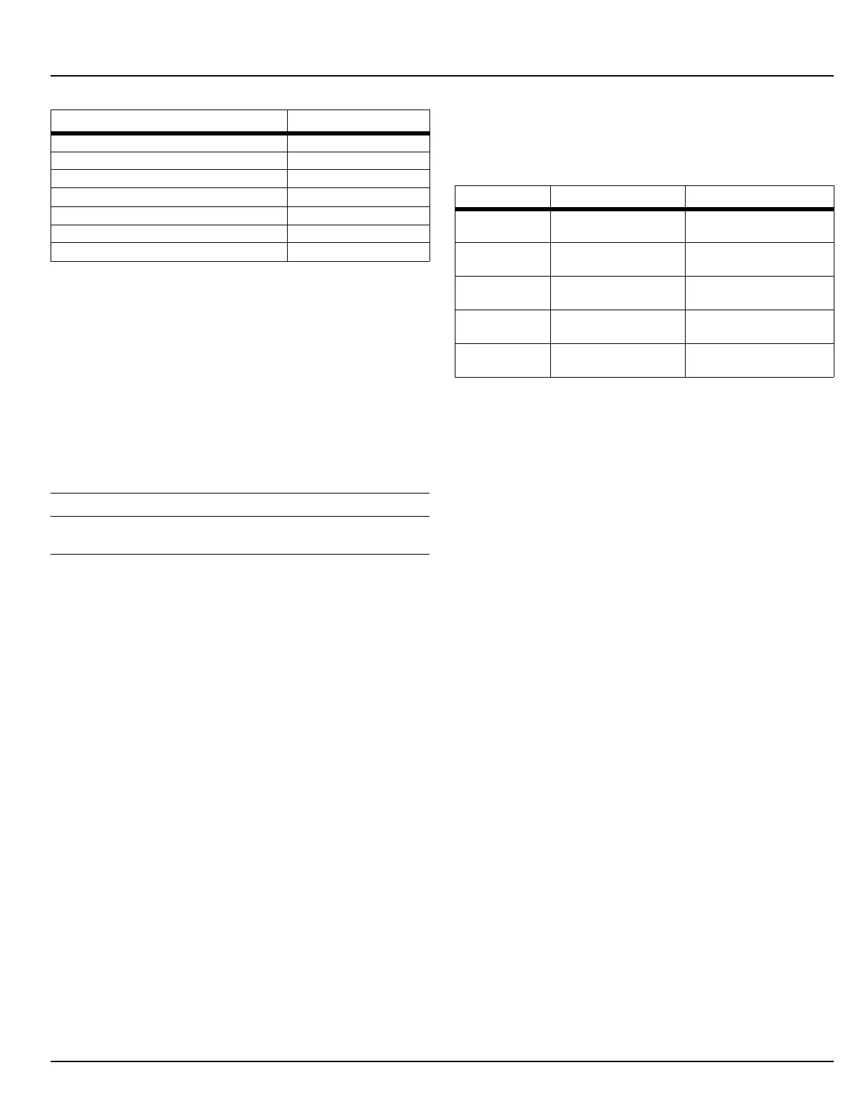
Table 5. Controller Statistics (Continued)
Statistic Range
Table 6. File Nomenclature
File Nomenclature Description
ARC00000.csv ARC=Archive
00000=Serial number
Message history
STC00000.txt STC=Statistics
00000=Serial number
Controller statistics
DIA00000.txt DIA=Diagnostics
00000=Serial number
Controller diagnostics
STA00000.txt STA=Statistics
00000=Serial number
Controller status
CON00000.txt CON=Configuration
00000=Serial number
Controller configuration
 Loading...


