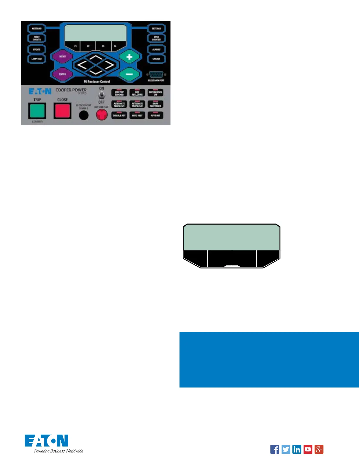
Basic control operations
• CHANGE: The CHANGE key must be pressed prior to actuating
any of the nine (9) Function Key Buttons.
NOTE: The CHANGE key remains active for 10 seconds after which
time the LCD display returns to the basic menu.
• LAMP TEST: When the LAMP TEST feature is actuated, all front
panel LEDs will illuminate for approximately five seconds.
• TRIP: Pressing the TRIP pushbutton trips the recloser to
the “RECLOSER OPEN” position and places the control in
“CONTROL LOCKOUT” mode (automatic reclosing is inhibited).
• CLOSE: Pressing the CLOSE pushbutton closes the recloser. The
control is now ready to follow OCP programming.
Hot Line Tag
Provided for live-line work applications.
• Does not cause the recloser to trip open. It only prevents the
recloser from closing.
• Prevents all closing attempts from the control and shifts
protection to one trip-to-lockout on the composite curve of the
Hot Line Tag definite time and the TCC1 curve (whichever is
faster). Takes precedence over Cold Load Pickup, Non-Reclosing,
and Fast Trips Disabled.
• Activated from either the operator front panel toggle switch, local
or remote communications, or configurable logic.
• Can only be reset by the source which initiates it.
• When hot line tag is enabled from either device, the AST is
DISABLED and the AST system will not transfer automatically.
AST function key buttons
Also, refer to the “CHANGE” key description.
• DISABLE AST button is used to manually disable the AST
function. A red LED indicates the AST is disabled. Possible
alternate causes are Hot Line Tag, Overcurrent Trip, or
Communications Failure.
• AUTO REST will put the AST into “automatic restoration” mode.
When activated without AUTO INIT, this mode will wait for
the operator to initiate the restoration by operating one of the
devices. The system will automatically perform the alternative
action on the remote device.
• AUTO INIT will put the AST in “automatic restoration with
automatic initiation” mode. When activated this mode will
automatically return the system to the preferred configuration
given the voltage on the preferred source is within acceptable
limits and the user-definable time has expired.
NOTE: AUTO REST must be active to use AUTO INIT.
NOTE: If the AST is in neither the AUTO REST nor the AUTO INIT
modes then the AST system is in a completely manual restoration
mode. Operations on each control need to be initiated separately to
bring the system back to the AST READY state.
• SWAP PREFERRED, when activated, will swap which device is
the preferred source for the critical load.
IMPORTANT: If SWAP PREFERRED is pressed while the system is
AST READY and AUTOMATIC RESTORATION mode is enabled, the
devices will open and close respectively to keep the system in AST
READY state.
View / change settings
1. Press the SETTINGS hotkey, the LCD will display: “Mod/View
Settings.”
2. Press the ENTER key, the LCD will display « Enter Password «.
The default password is «0» - therefore, if a password has not
been assigned just press the ENTER key again, otherwise, enter
your password and then press ENTER.
HINT: Use the + and – keys to enter a password. Press-and-hold the
key to skip through the values faster.
Accept / cancel settings change
Following a settings change press the ENTER key and then the
MENU key – the screen shot shown below will be displayed.
SELECT AN OPTION FOR
THE ALTERED SETTINGS:
USE REVERT BACK
If you made a change to one or more settings either:
Accept and USE a changed setting – press the F1 function key.
• REVERT to the previously saved setting – press the F2 function
key.
• Step BACK to the previous dialog – press the F4 function key.
For assistance, contact the
Switchgear Support Group at
1-800-497-5953. 24/7
emergency support also available.
Eaton
1000 Eaton Boulevard
Cleveland, OH 44122
United States
Eaton.com
Eaton’s Power Systems Division
2300 Badger Drive
Waukesha, WI 53186
United States
Eaton.com/cooperpowerseries
© 2018 Eaton
All Rights Reserved
Printed in USA
Publication No. MZ280004EN /
CSSC-1809-6025
KA20480732 REV 01
November 2018
Supersedes March 2014 (B280-14046)
Follow us on social media to get the
latest product and support information.
Eaton is a registered trademark.
All other trademarks are property
of their respective owners.

 Loading...


