SV9000 Motor Pump Enhanced Protection Application Page 19 (60)
6.2 Description of Groups 2-10 Parameters
6.2.1 Group 2, Analog Input Signal Parameters
2.1 V
in
signal range
0 = Signal range 0—+10 V
1 = Custom setting range from custom minimum (par. 2.2) to custom maximum (par. 2.3)
2 = Signal range -10—+10 V , can be used only with Joystick control
2.2- V
in
custom setting minimum
2.3 V
in
custom setting maximum
With these parameters, V
in
can be set for any input signal span within 0—10 V.
Minimum setting: Set the V
in
signal to its minimum level, select parameter 2.2, press the
Enter button
Maximum setting:Set the V
in
signal to its maximum level, select parameter 2.3, press the
Enter button
Note! These parameters can only be set with this procedure (not with arrow up/arrow
down buttons)
2.4 V
in
signal inversion
0 = no inversion of analog V
in
signal.
1 = inversion of analog V
in
signal.
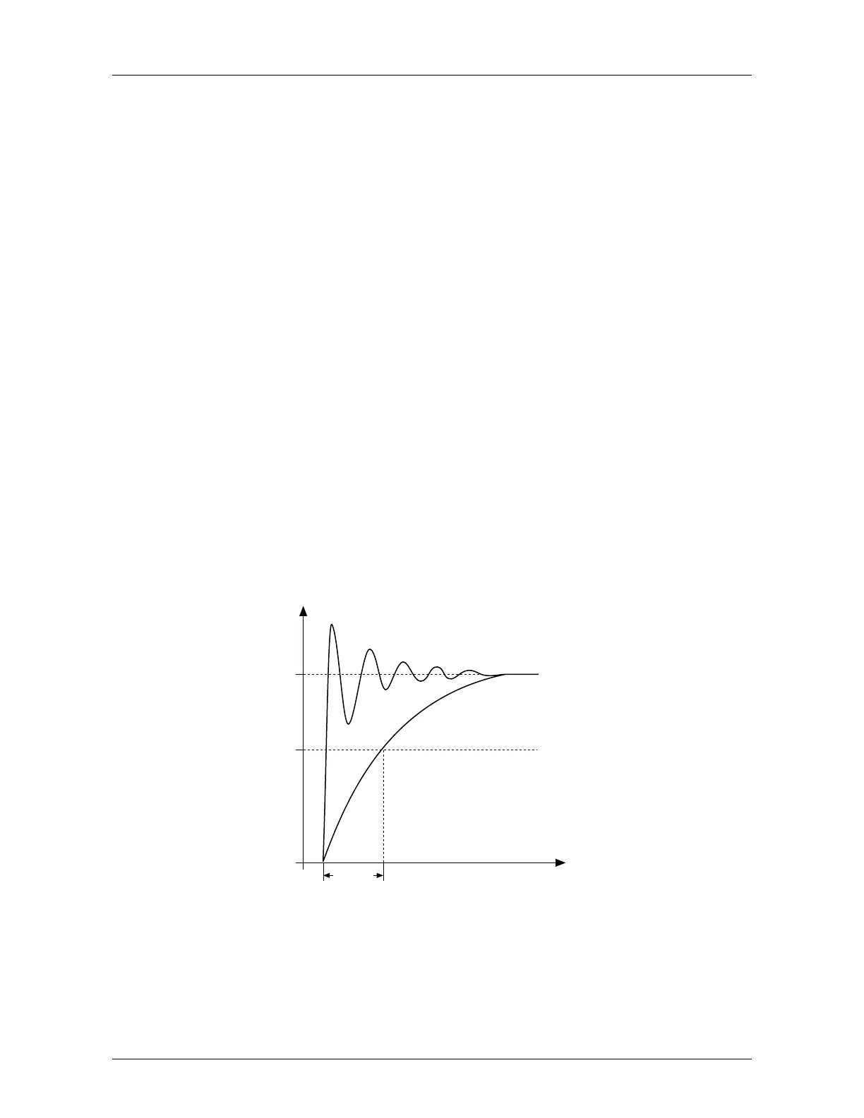
2.5 V
in
signal filter time
Filters out disturbances from the incoming analog V
in
signal. Long filtering time makes
regulation response slower. See figure 6.2-1.
t(Sec.)
Unfiltered signal
%
100%
63%
Filtered signal
Par. 2.5
Figure 6.2-:1 V
in
Signal Filtering
2.6 Analog input I
in
signal range
0 = 0—20 mA
1 = 4—20 mA
2 = Custom signal span
 Loading...


