17
Chapter 2: Motherboard Installation
1 Locate the F_USB1/F_USB2 headers on the motherboard.
2 Plug the bracket cable onto the F_USB1/F_USB2 headers.
3 Remove a slot cover from one of the expansion slots on the system
chassis. Install an extension bracket in the opening. Secure the
extension bracket to the chassis with a screw.
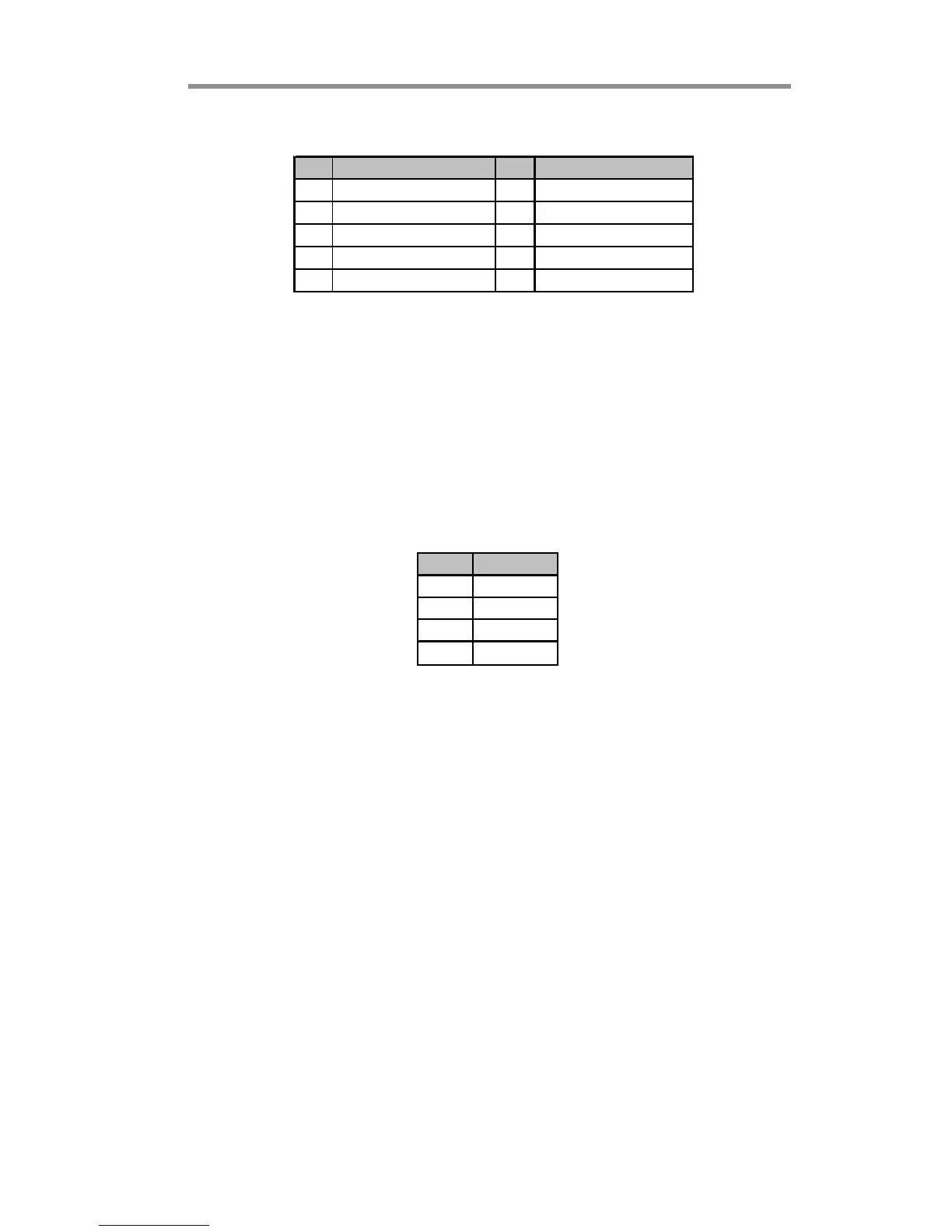
Pin Signal Pin Signal
1 USBPWR 2 USBPWR
3 USB_FP_P0(-) 4 USB_FP_P1(-)
5 USB_FP_P0(+) 6 USB_FP_P1(+)
7GND 8GND
9 KEY 10 USB_FP_OC0
Here is a list of headers F_USB1/F_USB2 pin assignments.
SPDIFO1: SPDIF Out Header
This is an optional header that provides an S/PDIF (Sony/Philips Digital Interface)
output to digital multimedia device through optical fiber or coxial connector.
Pin Signal
1SPDIFOUT
2+5V
3Key
4GND
 Loading...