WARNING: Before performing any maintenance, make sure that the battery pack is removed.
Failure to heed this warning could result in serious personal injury.
WARNING: Always wear gloves when handling the bar and chain; these components are sharp and
may contain burrs.
WARNING: Never touch or adjust the chain while the motor is running. The saw chain is very sharp;
always wear protective gloves when performing maintenance to the chain.
Disassembling the worn chain
1. Remove the battery, allow the pole saw to cool
and tighten the oil-tank cap.
2. Position the pole saw attachment on its side on
a firm, flat surface, so that the chain-sprocket
cover is facing upwards (Fig. 1).
3. Wear gloves. Using the dual-head wrench
provided, loosen the cover screw assembly
and remove it from the chain-sprocket cover.
4. Remove the chain-sprocket cover from the
pole saw attachment. Clean the chain-sprocket
cover with a dry cloth.
5. Remove the bar and chain from the mounting surface. Remove the worn chain from the bar.
NOTICE: If there is difficulty in removing the bar and chain from the mounting surface, place the pole saw
upright, with one hand supporting the bar, and loosen the chain-tensioning screw counterclockwise with the
other hand (Fig. 2). Then remove the bar with the chain.
Assembling the bar and new chain
1. Lay the new saw chain in a loop on a flat surface and straighten any kinks (Fig. 3).
NOTICE: This is a good time to inspect the drive sprocket for excessive wear or damage.
2. Place the chain drive links into the guide-bar
groove. Position the chain so there is a loop at
the back of the guide bar (Fig. 4).
3. Hold the chain in position on the guide bar and
place the loop around the sprocket of the pole
saw.
NOTICE: Small directional arrows are engraved in the saw chain. Another directional arrow is molded
into the tool body (Fig. 5a). When looping the saw chain onto the sprocket, make sure that the direction of
the arrows on the saw chain will correspond to the direction of the arrow on the tool body. If they face in
opposite directions, turn over the saw chain and guide bar assembly (Fig. 5b).
4. Place the guide bar on the mounting surface by sliding the guide-bar slot over the alignment bulges,
making sure that the tension-adjusting pin is inserted in the lower hole in the tail of the bar (Fig. 5a).
NOTICE: If there is difficulty in inserting the tension-adjusting pin into the hole, adjust the chain-tensioning
screw properly until the tension-adjusting pin is located exactly in the hole.
5. Replace the chain-sprocket cover, insert the cover-screw assembly through its mounting hole, and
then lightly tighten the chain-sprocket cover-screw by turning it clockwise. The bar must be free to
move for tension adjustment.
CAUTION: The saw chain must be properly tensioned before using.
NOTICE: To extend the guide bar life, invert the bar occasionally.
6. Remove all the slack from the chain by turning the chain-tensioning screw clockwise until the chain
seats snugly against the guide bar with the drive links in the guide-bar groove (Fig. 6).
7. Lift the tip of the guide bar to check for sag (Fig. 7). Release the tip of the guide bar and turn the
chain tensioning screw once clockwise. Repeat this process until the sag is eliminated.
8. Hold the tip of the guide bar up and tighten the chain-sprocket cover screw securely. The chain is
correctly tensioned when there is no sag on the underside of the guide bar and the chain is snug, but
it can be turned by hand without binding.
NOTICE: If the chain is too tight, it will not rotate. Loosen the chain-sprocket-cover screw slightly and
turn the tensioning screw 1/4 turn counterclockwise. Lift the tip of the guide bar and retighten the chain-
sprocket-cover screw securely. Assure that the chain will rotate without binding.
OPERATOR’S MANUAL
REPLACING THE SAW CHAIN
MODEL NUMBER AC1000
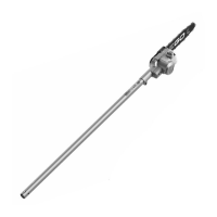
The saw chain is exclusively compatible with
EGO 10’’ Power Head System Pole Saw Attachment PSA1000.
1 2 3
7
Lift the Tip of the Guide
Bar Up to Check for Sag
6
1
Chain-sprocket Cover
Cover-screw
32
Chain-tensioning Screw
4
Chain Drive
Link
Guide-bar Groove
5b5a
Cut Direction
Tension-
adjusting Pin
Alignment
Bulges
Chain-tensioning
Screw
Guide-bar Slot
Rotation Direction Arrow
on the Tool Body
Sprocket
AVERTISSEMENT
:
Avant d’effectuer l’entretien, assurez-vous que le bloc-pile est retiré. Le non-
respect de cet avertissement peut occasionner des blessures graves.
AVERTISSEMENT
:
Portez toujours des gants lorsque vous manipulez le guide-chaîne et la chaîne,
étant donné que ces composants sont tranchants et peuvent comprendre des bavures.
AVERTISSEMENT
:
Ne touchez ni n’ajustez jamais la chaîne pendant que le moteur tourne. La
chaîne de la scie est très tranchante; portez toujours des gants de protection lorsque vous en effectuez
l’entretien.
Démontage de la chaîne usés
1. Retirez le bloc-pile, laissez la scie à rallonge
refroidir et serrez le capuchon du réservoir
d’huile.
2. Placez la scie à rallonge amovible sur le côté
sur une surface solide et plane, de façon que
le couvercle du pignon d’entraînement soit
vers le haut (Fig. 1).
3. Portez des gants. En utilisant la clé à double
tête fournie, desserrez l’assemblage du
couvercle et retirez-le du couvercle du pignon
d’entraînement.
4. Retirez le couvercle du pignon d’entraînement de la scie à rallonge amovible. Utilisez un linge sec
pour nettoyer le couvercle du pignon d’entraînement.
5. Retirez la chaîne et le guide-chaîne à partir de la surface de montage. Retirez la chaîne usée de la
chaîne.
AVIS : Si vous avez des difficultés à retirer la chaîne et le guide-chaîne à partir de la surface de montage,
placez la scie à rallonge en position verticale, une main soutenant le guide-chaîne, et l’autre desserrant la
vis de tensionnage de la chaîne dans le sens contraire des aiguilles d’une montre (Fig. 2). Retirez ensuite la
chaîne et le guide-chaîne.
Assemblage du nouveau guidechaîne et
de la nouvelle chaîne
1. Faites une boucle sur une surface plane avec la
nouvelle chaîne en redressant tout pli (Fig. 3).
AVIS : Le moment est bien choisi pour vérifier
l’absence d’usure ou de dommages excessifs sur le
pignon d’entraînement.
2. Insérez les maillons d’entraînement dans la
rainure du guide-chaîne. Positionnez la chaîne
de la scie de façon qu’une boucle se forme à
l’arrière du guide-chaîne (Fig. 4).
3. Tenez la chaîne en place sur le guide-chaîne et entourez le pignon d’entraînement de la scie à
rallonge avec la boucle.
MANUEL D’UTILISATION
REMPLACEMENT DE LA CHAÎNE
NUMÉRO DE MODÈLE AC1000
La chaîne est compatible exclusivement avec
EGO POWER+ SCIE À RALLONGE AMOVIBLE PSA1000.
1
Couvercle du pignon d’entraînement
Cache-vist
32
Vis de tensionnage
de la chaîne
4
Maillons
d’entraînement
Rainure du guide-chaîne