All plug-in modules and blank plates are part of the
re enclosure and must be removed only when a
replacement can be added immediately. The system
must not be run without all parts in place.
4A controller must be operated only from a
power supply input voltage range of 100–240
VAC, 50–60 Hz.
4Each component is intended to operate with
two working power supplies installed.
4Provide a suitable power source with electrical
overload protection.
4A safe electrical earth connection must be pro-
vided to the power cord. Check the grounding
of the power sources before applying power.
4The plug on each power supply cord is used
as the main disconnect device. Ensure that the
socket outlets are located near the equipment
and are easily accessible.
4Permanently unplug the unit if you think it is
damaged in any way and before moving it. If
powered by multiple sources, disconnect all
supply power for complete isolation.
4The power connections must always be
disconnected prior to removal or replacement
of a power supply module from any of the
components in the system.
4A faulty power supply module must be replaced
within 24 hours.
4Do not lift system components by yourself. A
controller weighs up to 57 lbs (25.8 kg).
4To comply with applicable safety, emission,
and thermal requirements, no covers should
be removed and all bays must be tted with
plug-in modules.
4Load the rack beginning at the bottom to
prevent the rack from becoming top-heavy.
4Do not extend components on rails until you
have loaded at least three or more similarly
weighted items in the rack, or unless the rack
is bolted to the oor or overhead structure to
prevent tipping.
Caution: If the system is used in a manner not
specied by the manufacturer, the protection provided
by the equipment may be impaired.
Caution: The RJ-45 sockets on the motherboard/PCI
cards are for Ethernet connection only and must not be
connected to a telecommunications network.
ESD PRECAUTIONS
Data Domain recommends that you t and check a
suitable anti-static wrist or ankle strap and observe
all conventional ESD precautions when handling
plug-in modules and components.
Safety
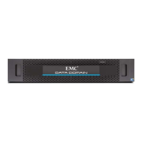
1. Unpack the Data Domain system.
A system consists of a DD620 controller and either seven 1 TB internal
disk drives providing 7 TB of raw capacity, or twelve 1 TB disk drives
providing 12 TB raw capacity, congured as RAID 6.
4Open the packing box for the controller.
4Remove the accessories and rack mount kit for all system components.
2. Install the appropriate rack mounting hardware for the controller into a
19-inch, four-post rack. Ensure that the rack is securely anchored to prevent
tipping. Load the rack or cabinet beginning at the bottom to prevent the
rack from becoming top heavy. Be sure to plan appropriate vertical space to
accommodate the 2U controller.
See the instructions included with the rackmount rails.
3. Install the controller in the rack in a horizontal position.
4Remove the controller from the shipping box.
4Remove the bezel from the shipping package.
4Install the controller on the tray rails and slide it into the rack. Be sure
one person is at each side of the controller to guide it into the rail ends.
4Secure the controller in the rack with the thumb screws.
4. Connect an administrative console. Attach a serial console to
the controller’s serial port, or use a monitor (VGA port) and keyboard
(keyboard/purple icon), or use a KVM. USB is not supported as a KVM
connection. See Figure 1.
After physically connecting the Null Modem Serial cable to the 9-pin serial
port on the Data Domain system and to the serial port on the client, set
communication parameters of the client (HyperTerminal, PuTTY, etc) as
follows:
Baud rate: 9600 Stop Bits: 1
Bits: 8 Flow Control: None
Parity: None Terminal Emulation: VT-100
5. Enable data transfer connectivity. Repeat for each connection.
4Ethernet connection: If using 1 Gb copper Ethernet, attach a Cat 5e or
Cat 6 copper Ethernet cable to an RJ45 Ethernet network port (start
with eth0a and go up) on the controller and attach the other end to an
Ethernet switch or to an Ethernet port on your server. If using
1 Gb ber Ethernet, use multimode ber cables with LC connectors.
See Figure 1.
4Fibre Channel connection: If the system has the optional VTL card,
attach a Fibre Channel ber optical cable (LC connector) to a VTL HBA
port on the controller, and attach the other end (LC connector) to a
Fibre Channel switch or to a Fibre Channel port on your server. See
Figure 1 for PCI card locations for the VTL HBAs.
6. Provide redundant power to the system.
Connect power cables to both receptacles. See Figure 1.
7. Turn the system on.
4When the Alert/ID LED turns blue, press the power button. See Figure 2.
4Attach the bezel.
8. Collect the information needed for installation. Enter the information in
Section 2 on the other side of this sheet.
Install Hardware
1
The steps for a complete installation and conguration are:
1. Install Hardware
2. Dene the Data Domain system information for your site
3. Perform initial system conguration
4. Congure the system for data access
5. Congure optional software
6. Perform optional additional system conguration
Installation and Setup Steps
1
5
4
3
2
6
Installation and Setup Guide
EMC DATA DOMAIN DD620 STORAGE SYSTEM