EMC
®
VNXe
®
Replacing an input/output module in a disk
processor enclosure
302-000-207
REV 02
July, 2015
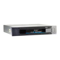
This document describes how to replace a faulted input/output (I/O) module in a DPE (disk
processor enclosure).
The I/O module resides on the SP printed circuit board (CPU board). To replace a faulted
I/O module, you must remove the SP assembly from the enclosure, and then remove its
cover to gain access to CPU board components.
You access an I/O module from the rear of the enclosure.
Always replace an I/O module with one that is the exact same type. Verify the type by
reading the label on the I/O module handle.
This procedure involves storage processor (SP) reboots coordinated to ensure that at least
one SP is running at all times. During an SP reboot, data will be unavailable to front- or
back-end connections that are not duplicated on the peer SP.
l
Before you start..........................................................................................................2
l
Handling I/O modules................................................................................................2
l
Replacing the faulted hardware component............................................................... 5
l
Returning a faulted part........................................................................................... 12