3
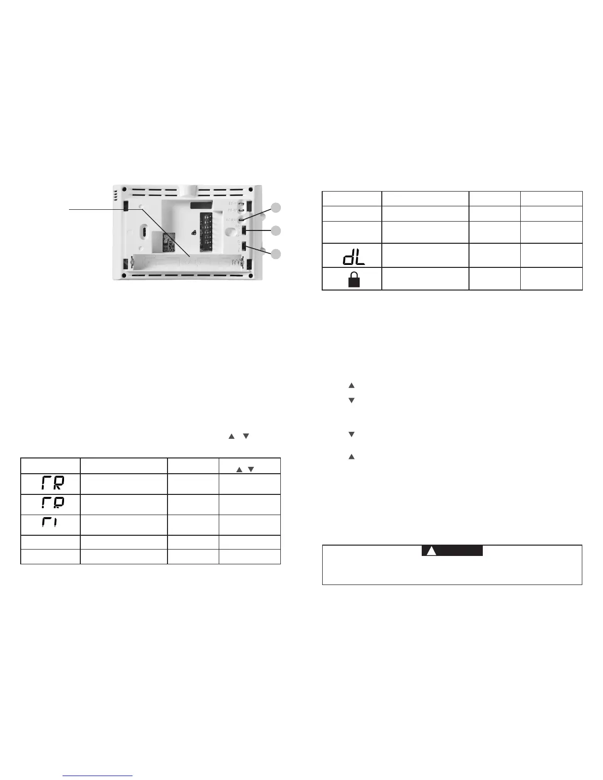
1.) Gas/Elec Switch
If the system is a heat pump or electric furnace, the GAS/ELEC Switch must be set to
Elec. If your system is a gas or oil furnace, the switch must be set to Gas.
2.) O/B Terminal Switch
The O/B switch on this thermostat is factory set to the O position. This will accommodate
the majority of heat pump applications, which require the changeover relay to be
energized in Cool. If the heat pump being installed requires a B terminal, to energize the
changeover relay in Heat, the O/B switch must be moved to the B position.
3.) RC/RH Jumper Wire
This thermostat electrically connects the RC and RH terminals so a jumper wire is not
required. If the application provides a separate wire for RC and RH, clip the RC/RH
jumper. This will isolate both terminals so they can be independently used.
INSTALLER MENU
To prevent changes that may aect system performance, this thermostat has an INSTALLER’S
MENU and an USER MENU. The INSTALLER’S MENU provides access to every option, while
the USER MENU provides access to items that will not aect system performance. To access
the INSTALLER’S MENU press the Menu button for 8 seconds. The display will show item 30 in
the table below. Use Next and Back to navigate through menu items. Press or to change
a menu setting.
Installer’s Menu #
(Hold Menu 8 Seconds)
Description
Default Setting
(ashing icons)
Settings
(Press or )
30
Heat Cycle Rate (how often
the heat will turn on)
MEd
SLO – slow
MEd – medium
FAS – fast
35
Cool Cycle Rate (how often
the cooling will turn on)
MEd
SLO – slow
MEd – medium
FAS – fast
50
Compressor Lockout
(protects the compressor
from short cycling)
OFF
On – 5 minute display
OFF – no delay
65
Maximum Heat Limit
(maximum set point for heat mode)
99 47 to 99
66
Minimum Cool Limit (minimum
set point for cool mode)
45 45 to 97
(Installer Menu continued on next page)
1
3
2
Baery Locaon
Premium AA alkaline batteries
are required when C-wire is
not available. When C-wire is
available, the batteries provide
a back-up source of power (this
will maintain the clock in the
event of a power outage).
4
Installer’s Menu #
(Hold Menu 8 Seconds)
Description
Default Setting
(ashing icons)
Settings
79
Fahrenheit or Celsius °F
°F – Fahrenheit
°C – Celsius
81
Temperature Display
Adjustment (adjust the displayed
“Room Temperature”)
0 -5 to +5
83
Continuous Display Light (keep
the backlight always on – “C” wire
required)
OFF
On – always on
OFF – momentarily
99
Keypad Lock (prevent unwanted
changes to the thermostat)
OFF
On – disable buttons
OFF – all buttons are
active
INSTALLER MENU (C0ntinued)
TEST EQUIPMENT
Turn on power to the system.
Fan Operation
If your system does not have a G terminal connection, skip to Heating System.
1.) Move fan switch to On position. The blower should begin to operate.
2.) Move fan switch to Auto position. The blower should stop immediately.
Heating System
1.) Move System Switch to Heat position.
2.) Press to adjust thermostat setting to 1° above room temperature. The system should
begin to operate and the thermostat will indicate Heat On.
3.) Press to adjust thermostat setting 1° below room temperature. The heating system
should stop operating and the thermostat should indicate Heat.
Cooling System
1.) Move System Switch to Cool position.
2.) Press to adjust thermostat setting 1° below room temperature. The blower should
come on immediately on high speed, followed by cold air circulation. The thermostat will
indicate Cool On. There can be up to a 5 minute delay. (see INSTALLER MENU, item 50)
3.) Press to adjust thermostat setting to 1° above room temperature. The cooling system
should stop operating and the thermostat will indicate Cool.
Note: If Starting Soon is shown on the display, the compressor lockout feature is operating.
There will be up to a 5 minute delay before the compressor turns on.(see INSTALLER MENU,
item 50)
 Loading...