Operating instruction
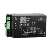
Compressor Soft Starter CSS-Series
Emerson Climate Technologies GmbH www.emersonclimate.eu
Am Borsigturm 31 I 13507 Berlin I Germany Date: 26.01.2016 CSS_OI_ML_R08_865724.docx
General information:
Compressor Soft Starters of the CSS-Series are used to limit the start current of 1-
phase compressors. For additional start torque a built-in start capacitor is switched in
parallel to the run capacitor. After start it is switched off. Supply voltage is
continuously monitored. In case of under voltage the compressor is switched off.
Restarts are delayed and indicated by a blinking greed LED. In case of alarm a signal
is indicated by the red LED. The alarm relay will be activated.
Soft starters are released for use with many compressors. (See list Fig.3).
CSS-32U / CSS-32W for compressor motors with nominal current up to 32A
CSS-25U for compressor motors with nominal current up to 25A
Safety instructions:
• Read operating instructions thoroughly. Failure to comply can result in device
failure, system damage or personal injury.
• According to EN 13313 it is intended for use by persons having the
appropriate knowledge and skill.
• Do not exceed the specified maximum ratings for pressure, temperature,
voltage and current.
• Before installation or service disconnect all voltages from system and device.
• Unauthorized opening of the CSS will void warranty.
• Entire electrical connections have to comply with local regulations.
• Do not operate system before all cable connections are completed.
Disposal: Electrical and electronic waste must NOT be disposed of with other
commercial waste. Instead, it is the user responsibility to pass it to a designated
collection point for the safe recycling of Waste Electrical and Electronic
Equipment (WEEE directive 2002/95/EC). For further information, contact
your local environmental recycling center.
Setting:
• No setting required. The Soft Starters automatically limit the start current based on
the connected compressor size. Several consecutive starts are required to learn and
optimize the start current of the attached compressor.
Mounting – Dimensions See Fig. 2,4:
• CSS Soft Starters are for mounting in electrical switch boards only. The mounting
clip allows convenient DIN rail fixing; for secure mounting on any other flat
surface, it has four drill holes (Ø4.5 mm). The mounting clip can be attached to the
housing base in two directions, see fig. 4.
• Protect CSS from direct sun light and water.
Wiring (Fig. 1,2):
Warning:
• Use automatic circuit breaker F with characteristic of circuit control C.
Releasing current 25A for CSS-25U, 32A for CSS-32U / CSS-32W.
• Do not use an additional contactor. CSS could be damaged.
• Do not connect “Crun” capacitor to the "Run" lead of the motor. Connect it
between RC and S terminals as per wiring diagram. An additional start
capacitor “Cstart” is built in the Soft Starter
• Perform wiring as printed on the housing. CSS Contacts:
Start input (“on” if connected to 230V)
• The terminals are for flexible cable cross section 0.25 … 4 mm
2
.
CSS-32W R- RC and L contacts: 0.25 … 6 mm
2
• The screws must be tightened with 0.5… 0.6 Nm.
• The wiring diagram per Fig.1 is an example how safety functions can be wired.
Circuit breaker of control circuit
Operation:
• After all connections are wired, supply voltage can be switched on. Green + red
LED will be on for 30 sec after power up, then blinking green LED indicates the
initial delay time of 150 sec. Green LED on will indicate “ready for start”.
• Switch contact "Uc" to 230V (for min. 0.5 sec) starts the motor with limited start
current. The start sequence is monitored.
• If the motor does not start, it is switched-off. A restart will be delayed for 5 Min.
A blinking green LED indicates the delay.
• The compressor is switched-off, when "Uc" is disconnected from 230V. A restart
will be delayed. This is indicated by a blinking green LED. After elapsed delay
time the green LED will stop blinking; a restart is possible instantly.
• For other messages see list of LED indicator codes below
Technical Data:
230 V AC +10% / -15% / 50/60 Hz
Continuous compressor current, max.
CSS-25U: 25 A
CSS-32U / CSS-32W: 32 A
Compressor start current limited to max.
45 A / (30 A pcn 805209-805210)
230 V AC +10% / -15% / 50/60 Hz
Resistive (AC1) max.
Flexible cable cross section CSS-32W, (R, RC, L)
Flexible cable cross section (power lines)
Flexible cable cross section (alarm outp.)
Vibration resistance (10 ... 1000 Hz)
Standards
• Low voltage directive LVD 2006/95/EC
• Contactors and motor-starters - AC semiconductor motor controllers and starters
EN60947-4-2
• Safety for household (Part. No. 805204, 805205 only): EN60335-2-40
• Electromagnetic Compatibility: EMC 2004/108/EC
• RoHS 2011/65/EU
2
• Marking:
Product information per EN 60947-4 - 2
Manufacturer: Emerson Climate Technologies GmbH
Type codes: CSS-25U CSS-32U CSS-32W
Nom. operating current: 25A 32A max. / AC-53a; AC-58a
Operating voltage / Frequency: 230V nom / 50/60Hz
Operation category: 32A, Class 12, 60%
Device alternative: Hybrid motor starter with bypassed semiconductor
Isolation voltage: 2.5 kV
Surge voltage: 1.5 kV
Protection acc. IEC 529 IP-20
Pollution degree: 2
LED Indicator Codes
System energized, normal operation
Compressor might be ON or OFF
System energized, waiting for delay time elapsed
System test after power on
System cannot start caused by low voltage condition
Blink frequ. 2.5 Hz, 1.5 sec break between blink packages
Start winding voltage too low after start sequence
Motor current too high (32 A eff)
Start capacitor error (damaged or disconnected)
Blink frequ. 2.5 Hz, 1.5 sec break between blink packages
Start capacitor or run capacitor error (defect relay)
Perform reset; exchange CSS if problem persists
check wiring of R, RC and S terminals
Severe problems, device to be replaced
System not energized or internal power supply defect
If energized device to be replaced
Main circuit breaker blown at power on
Remove compressor lines R and RC; switch power on for few sec. Reconnect
compressor and power on again. (Note: Shock and vibrations
at transport can set bistable relays into wrong position. With this mode the relays will be reset to the correct position).