1592023020 XM660K_XM669K GB r1.0 07.01.2013.doc XM660K - XM669K 1/8
CONTROLLERS FOR MULTIPLEXED CABINETS
XM660K- XM669K
CONTENTS
CONTENTS ____________________________________________________________________________ 1
1.
GENERAL WARNING ________________________________________________________________ 1
2.
GENERAL DESCRIPTION ____________________________________________________________ 1
3.
USER INTERFACE __________________________________________________________________ 1
4.
FAST ACCESS MENU _______________________________________________________________ 2
5.
THE SECTION MENU ________________________________________________________________ 2
6.
REAL TIME CLOCK FUNCTIONS (If present) _____________________________________________ 2
7.
ELECTRONIC EXPANSION VALVE MENU (ONLY FOR XM669K) _____________________________ 2
8.
CONTROLLING LOADS ______________________________________________________________ 2
9.
PARAMETER LIST __________________________________________________________________ 3
10.
DIGITAL INPUTS ___________________________________________________________________ 5
11.
INSTALLATION AND MOUNTING ______________________________________________________ 5
12.
ELECTRICAL CONNECTIONS _________________________________________________________ 5
13.
RS485 SERIAL LINE _________________________________________________________________ 6
14.
USE OF THE PROGRAMMING “HOT KEY“ _______________________________________________ 6
15.
ALARM SIGNALS ___________________________________________________________________ 6
16.
TECHNICAL DATA __________________________________________________________________ 6
17.
CONNECTIONS ____________________________________________________________________ 6
18.
DEFAULT SETTING VALUES _________________________________________________________ 6
1. GENERAL WARNING
1.1
PLEASE READ BEFORE USING THIS MANUAL
• This manual is part of the product and should be kept near the instrument for easy and quick
reference.
• The instrument shall not be used for purposes different from those described hereunder. It cannot
be used as a safety device.
• Check the application limits before proceeding.
•
Dixell Srl reserves the right to change the composition of its products, even without notice,
ensuring the same and unchanged functionality.
1.2
SAF
E
TY PRECAUTIONS
• Check the supply voltage is correct before connecting the instrument.
• Do not expose to water or moisture: use the controller only within the operating limits avoiding
sudden temperature changes with high atmospheric humidity to prevent formation of
condensation
• Warning: disconnect all electrical connections before any kind of maintenance.
• Fit the probe where it is not accessible by the End User. The instrument must not be opened.
• In case of failure or faulty operation send the instrument back to the distributor or to “Dixell S.r.l.”
(see address) with a detailed description of the fault.
• Consider the maximum current which can be applied to each relay (see Technical Data).
• Ensure that the wires for probes, loads and the power supply are separated and far enough from
each other, without crossing or intertwining.
• In case of applications in industrial environments, the use of mains filters (our mod. FT1) in parallel
with inductive loads could be useful.
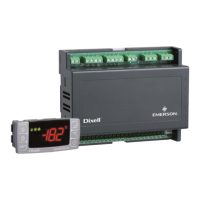
2. GENERAL DESCRIPTION
The XM660K/XM669K are high level microprocessor based controllers for multiplexed cabinets suitable
for applications on medium or low temperature. It can be inserted in a LAN of up to 8 different sections
which can operate, depending on the programming, as stand alone controllers or following the
commands coming from the other sections. The XM660K/XM669K are provided with 4 relay outputs to
control the solenoid valve, defrost - which can be either electrical or hot gas - the evaporator fans, the
lights and with one output to drive pulsed electronic expansion valves (only XM669K). The devices
are also provided with four probe inputs, one for temperature control, one to control the defrost end
temperature of the evaporator, the third for the display and the fourth can be used for application with
virtual probe or for inlet/outlet air temperature measurement. The model XM669K is provided by other
two probes that have to be used for superheat measurement and regulation. Finally, the
XM660K/XM669K are equipped with two digital inputs (free contact) fully configurable by parameters.
The instruments are equipped with the HOTKEY connector that permits to be programmed in a simple
way. Direct serial output RS485 ModBUS-RTU compatible permits a simple XWEB interfacing. RTC
are available as options. The HOTKEY connector can be used to connect X-REP display (Depending on
the model).
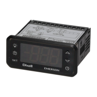
3. USER INTERFACE
To display and modify target set point; in programming mode it selects a parameter or
confirm an operation.
By holding it pressed for 3s when max or min temperature is displayed it will be
erased.
In programming mode it browses the parameter codes or increases the displayed
value.
By holding it pressed for 3s the give access to the “Section” menu.
By pressing and releasing this key you get the access to fast access menu
in programming mode it browses the parameter codes or decreases the displayed
value.
By pressing and releasing this key you can activate or deactivate the auxiliary output
By holding it pressed for 3s the defrost is started.
Switch ON and OFF the room light.
By pressing for about 3s switch ON and OFF the instrument.
Measurement unit
Measurement unit
Measurement unit
Measurement unit
KEY COMBINATIONS
To lock and unlock the keyboard.
To enter the programming mode.
+
To exit the programming mode.
3.1 USE OF LEDS
Each LED function is described in the following table.
ON
Compressor and valve regulation enabled, to see valve opening
percentage you should see the fast access menu
Flashing Anti-short cycle delay enabled
ON Defrost enabled
Flashing Drip time in progress
ON An alarm is occurring
ON Energy saving enabled
ON The fan is running
Flashing Door opened or delay to restart fan after defrost
The auxiliary relay is ON
ON The controller is working in “ALL” mode
Flashing The controller is working in remote virtual display mode
Flashing During the CLOCK modification (if clock is present)
3.2 HOW TO ENTER INTO FAST ACCESS MENU
1. Press and release the o key.
2. First Label will be displayed. By pressing the o or n keys it’s possible to navigate
the menu
3.3 HOW TO SEE THE MAX AND MIN TEMPERATURE RECORDED
1. Press and release the o key.
2. First Label will be displayed. By pressing the o or n keys it’s possible to navigate
the menu. Search the L°t label and press SET to see minimum temperature; search
the H°t label and press SET to see maximum temperature;
3.4 HOW TO SEE AND MODIFY THE SET POINT
Push for about 3 seconds th
key: the display will show the Set point value;
2. The measurement unit starts blinking;
3. To change the Set value push the o or n arrows within 10s.
4. To store the new set point value push the SET key again or wait 10s.
3.5 HOW TO START A MANUAL DEFROST
Push the DEF key for more than 3 seconds and a manual defrost will start.
3.6 TO ENTER IN PARAMETERS LIST “PR1”
To enter the parameter list “Pr1” (user accessible parameters) operate as follows:
+
SET
Enter the Programming mode by pressing the SET
seconds (measurement unit starts blinking).
2. The instrument will show the first parameter present in “Pr1”
3.7 TO ENTER IN PARAMETERS LIST “PR2”
To access parameters in “Pr2”:
1. Enter the “Pr1” level.
2. Select “Pr2” parameter and press the “SET” key.
3. The “PAS” flashing message is displayed, shortly followed by “0 - -” with a flashing zero.
4. Use oor n to input the security code in the flashing digit; confirm the figure by pressing “SET”. The
security code is “321“.
5. If the security code is correct the access to “Pr2” is enabled by pressing “SET” on the last digit.
Another possibility is the following: after switching ON the instrument the user can push Set and DOWN
keys within 30 seconds.