SZ 1598030250 XR02CX RWA GB r1.2 29.08.2013.doc XR02CX 2/2
dA Exclusion of temperature alarm at startup: (0 to 99min) time interval between the detection
of the temperature alarm condition after instrument power on and alarm signalling.
OTHER
d1 Room probe instant value (read only)
d2 Evaporator probe instant value (read only)
rS Real Set Poin value (read only)
Pt Parameter code table (read only)
rL Software release (read only)
7 INSTALLATION AND MOUNTING
Instrument XR02CX shall be mounted on vertical panel, in a
29x71 mm hole, and fixed using the special bracket supplied.
The temperature range allowed for correct operation is 0 to 60°C.
Avoid places subject to strong vibrations, corrosive gases,
excessive dirt or humidity. The same recommendations apply to
probes. Let air circulate by the cooling holes.
8 ELECTRICAL CONNECTIONS
The instrument is provided with screw terminal block to connect cables with a cross section up to
2.5mm
2
. Before connecting cables make sure the power supply complies with the instrument’s
requirements. Separate the probe cables from the power supply cables, from the outputs and the
power connections. Do not exceed the maximum current allowed on each relay, in case of heavier
loads use a suitable external relay.
8.1 PROBES
The probes shall be mounted with the bulb upwards to prevent damages due to casual liquid
infiltration. It is recommended to place the thermostat probe away from air streams to correctly
measure the average room temperature. Place the defrost termination probe among the evaporator
fins in the coldest place, where most ice is formed, far from heaters or from the warmest place during
defrost, to prevent premature defrost termination.
9 HOW TO USE THE HOT KEY
9.1 HOW TO PROGRAM THE HOT KEY FROM THE INSTRUMENT
(UPLOAD)
1. Program one controller with the front keypad.
2. When the controller is ON, insert the “Hot-key” and push UP key; the "uP" message appears followed
a by flashing “En”
3. Push “SET” key and the “En” will stop flashing.
4. Turn OFF the instrument and then remove the “Hot-key”. After that turn it ON again.
NOTE: the “Er” message is displayed for failed programming. In this case push again o key if you want to
restart the upload again or remove the “Hot-key” to abort the operation.
9.2 HOW TO PROGRAM AN INSTRUMENT USING HOT KEY
(DOWNLOAD)
1. Turn OFF the instrument.
2. Insert a programmed “Hot Key” into the 5 PIN receptacle and then turn the Controller ON.
3. Automatically the parameter list of the “Hot-key” is downloaded into the Controller memory, the “do”
message is blinking followed a by flashing “En”.
4. After 10 sec the instrument will restart working with the new parameters.
5. Remove the “Hot-key”.
NOTE: the “Er” message is displayed for failed programming. In this case push again o key if you want to
restart the upload again or remove the “Hot-key” to abort the operation.
10 ALARM SIGNALLING
Mess. Cause Outputs
P1 Room probe failure Compressor output according to Cy e Cn
P2 Evaporator probe failure Defrost end is timed
HA Maximum temperature alarm Outputs unchanged
LA Minimum temperature alarm Outputs unchanged
5.1 ALARM RECOVERY
Probe alarms “P1” and “P2” start some seconds after the fault in the related probe; they automatically
stop some seconds after the probe restarts normal operation. Check connections before replacing the
probe. Temperature alarms “HA” and “LA” automatically stop as soon as the temperature returns to
normal values.
11 TECHNICAL DATA
Housing: self extinguishing ABS
Case: frontal 32x74 mm; depth 60mm
Mounting: panel mounting in a 71x29mm panel cut-out
Protection: IP20
Frontal protection: IP65
Connections: disconnectable terminal block 2.5 mm
2
wiring and 6.3mm fast-on
Power supply: according to the model ±10%; 230Vac 10%, 50/60Hz, 110Vac 10%, 50/60Hz
Power absorption: 3.5 VA max
Display: 2 digits, red LED, 14.2 mm high; Inputs: 2 NTC
Relay outputs: compressor SPST 8(3) A, 250Vac; 20(8)A 250Vac
Data storing: on the non-volatile memory (EEPROM).
Kind of action: 1B
Pollution degree: 2
Software class: A
Rated impulsive voltage: 2500V
Overvoltage Category: II
Operating temperature: 0 to 60°C (32 to 140°F)
Storage temperature: -30 to 85°C (-22 to 185°F)
Relative humidity: 20 to 85% (not condensing)
Measuring and regulation range: NTC -40 to 110°C (-40 to 230°F).
Resolution: 0.1°C or 1°C or 1°F (selectable)
Accuracy (ambient temp. 25°C): ±0.7°C ±1 digit
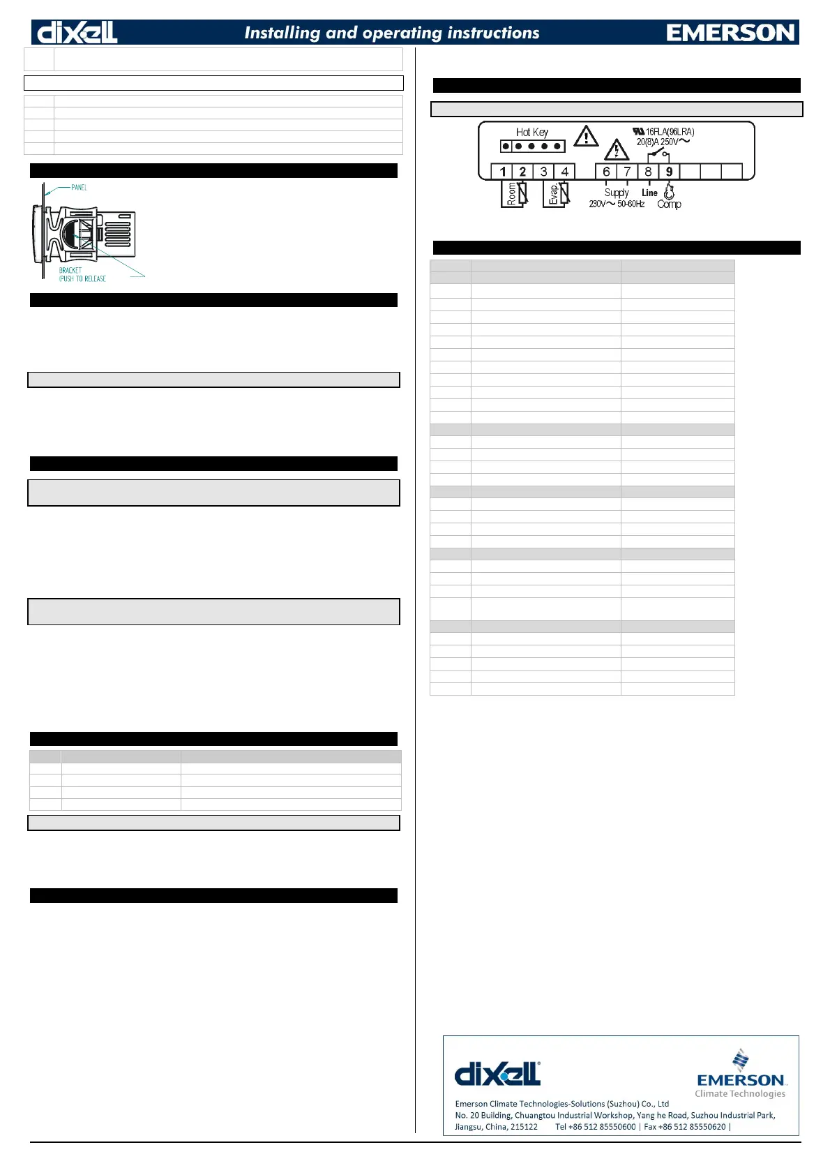
12 CONNECTIONS
12.1 20A COMPRESSOR RELAY
NOTE: in case of 110Vac model, connect power supply to terminals 6-7.
13 DEFAULT SETTING VALUES
LABEL DESCRIPTION RANGE
REGULATION
Hy Differential 0.1 to 25°C; 1 to 45°F
LS Minimum Set Point -55°C to SET; -67°F to SET
US Maximum Set Point SET to 99°C; SET to 210°F
ot First probe calibration -9.9 to 9.9°C; -17 to 17°F
P2 Second probe presence n; Y
oE Second probe calibration -9.9 to 9.9°C; -17 to 17°F
F5 Filter probe enabling nu; AL; do
od Outputs activation delay at start up 0 to 99 min
AC Anti-short cycle delay 0 to 50 min
Cy Compressor ON time faulty probe 0 to 99 min
Cn Compressor OFF time faulty probe 0 to 99 min
DISPLAY
CF Measurement units °C; °F
rE Resolution (only for °C) dE; in
Ld Default Display P1; P2
dy Display delay 0 to 15 min
DEFROST
dE Defrost termination temperature -50 to 50°C; -58 to 122°F
id Interval between defrost cycles 0 to 99 hours
Md Maximum length for defrost 0 to 99 min.
dF Display during defrost rt; in; dE
ALARMS
AU Maximum temperature alarm ALL to 99°C; ALL to 210°F
AL Minimum temperature alarm -55°C to ALU; -67°F to ALU
Ad Temperature alarm delay 0 to 99 min
dA
Exclusion of temperature alarm at
startup
0 to 99 min
OTHER
d1 Room probe display Read Only
d2 Evaporator probe display Read Only
rS Real set point Read Only
Pt Parameter code table Read Only
rL Firmware release Read Only

 Loading...