www.Fisher.com
Fisher
™
8532 High-Performance Butterfly Valve
Contents
Introduction 1.................................
Scope of Manual 1.............................
Description 1.................................
Specifications 2...............................
Educational Services 2.........................
Installation 4..................................
Valve Orientation 5............................
Before Installing the Valve 5.....................
Adjusting the Actuator Travel Stops or Travel 7.....
Installing the Valve 7...........................
Packing Adjustment and Shaft Bonding 9......
Maintenance 11................................
Removing and Replacing the Actuator 12.........
Packing Maintenance 12........................
Removing the Valve 13.........................
Seal Maintenance 14...........................
PTFE Seals 15.............................
NOVEX, Phoenix III and/or
Phoenix III Fire‐Tested Seals 16............
Anti‐Blowout Design, Packing, Valve Shaft,
Disk, and Bearing Maintenance 17.............
Installing the Two‐Piece Shaft 19.............
Gasket Retainer 21............................
Parts Ordering 22...............................
Parts List 24...................................
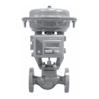
Figure 1. Fisher 8532 Valve with 1061 Actuator and
FIELDVUE™ DVC6200 Digital Valve Controller
W9138-1
Introduction
Scope of Manual
This instruction manual provides installation, maintenance, and parts information for NPS 14 through 24 Fisher 8532
high-performance butterfly valves.
Do not install, operate, or maintain an 8532 valve without being fully trained and qualified in valve, actuator, and
accessory installation, operation, and maintenance. To avoid personal injury or property damage, it is important to
carefully read, understand, and follow all the contents of this manual, including all safety cautions and warnings. If you
have any questions about these instructions, contact your Emerson sales office
or Local Business Partner before
proceeding.
Description
The valve is available in either a wafer (flangeless), lugged (single‐flange), or double flange body design, with a variety
of seals and internal components. The pressure‐assisted seal provides tight shutoff. The spline or keyed drive shaft
combines with a variety of actuators. Maximum inlet pressure/temperature ratings are consistent with CL150 and
CL300.
Instruction Manual
D101550X012
8532 Valve
June 2017