Safe Use Instructions – Emerson FloBoss 104 Flow Manager
Part D301733X012
February 2018
4 www.Emerson.com/RemoteAutomation
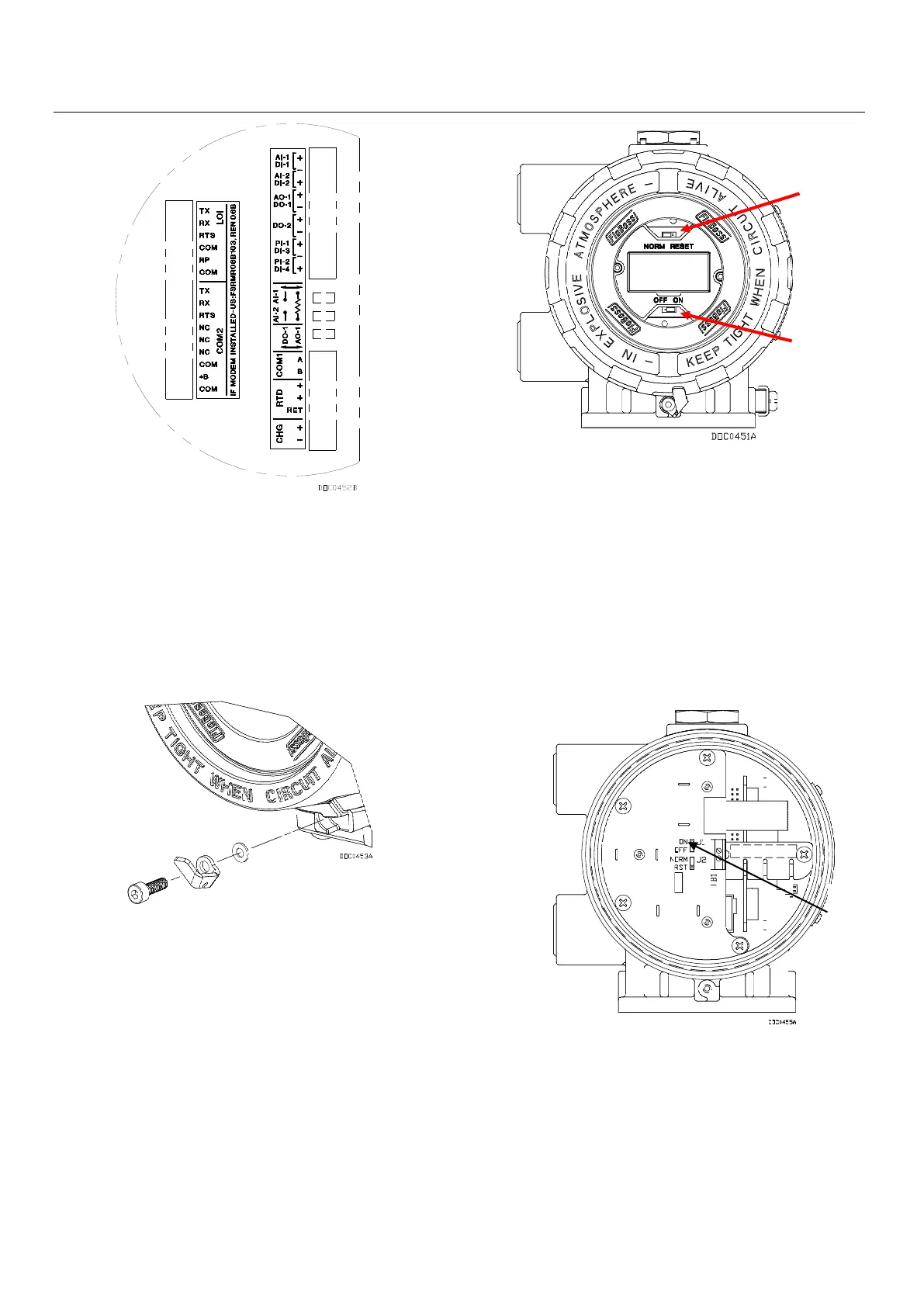
Figure 3. Termination Board
6. The FloBoss 104 ships with the NORM/RESET jumper
in the NORM position, and the ON/OFF jumper in the OFF
position.
To apply power to the FloBoss 104:
▪ Unscrew the cover clamp at the base of the front end
cap (LCD end). See Figure 4.
Figure 4. Cover Clamp Assembly
▪ Unscrew the front end cap cover.
▪ Place the power jumper (located on the LCD if
installed or located at J1 on the Battery Charger Board)
in the ON position. See Figure 5 and Figure 6.
Figure 5. Front End of FloBoss 103 (with LCD)
▪ Replace the front end cap cover (LCD end) and cover
clamp.
After the FloBoss 104 completes start-up diagnostics
(RAM and other internal checks), the optional LCD displays
the date and time to indicate that the FloBoss has
completed a valid reset sequence. If the LCD does not
come on, perform trouble-shooting for possible causes
(see Step 9).
Figure 6. Front End of FloBoss 104 (without LCD)
7. The FloBoss 104 must be configured before it is
calibrated and placed into operation. Configuration must
be performed using ROCLINK 800 software, which runs on
a PC. The PC is normally connected to the LOI port of the
flow computer to transfer configuration data into the
FloBoss 104, although much of the configuration can be
done off-line and later loaded into the FloBoss.

 Loading...


