3.4.3 Wire the mA/HART
®
multidrop installation (internally or
externally powered)
Procedure
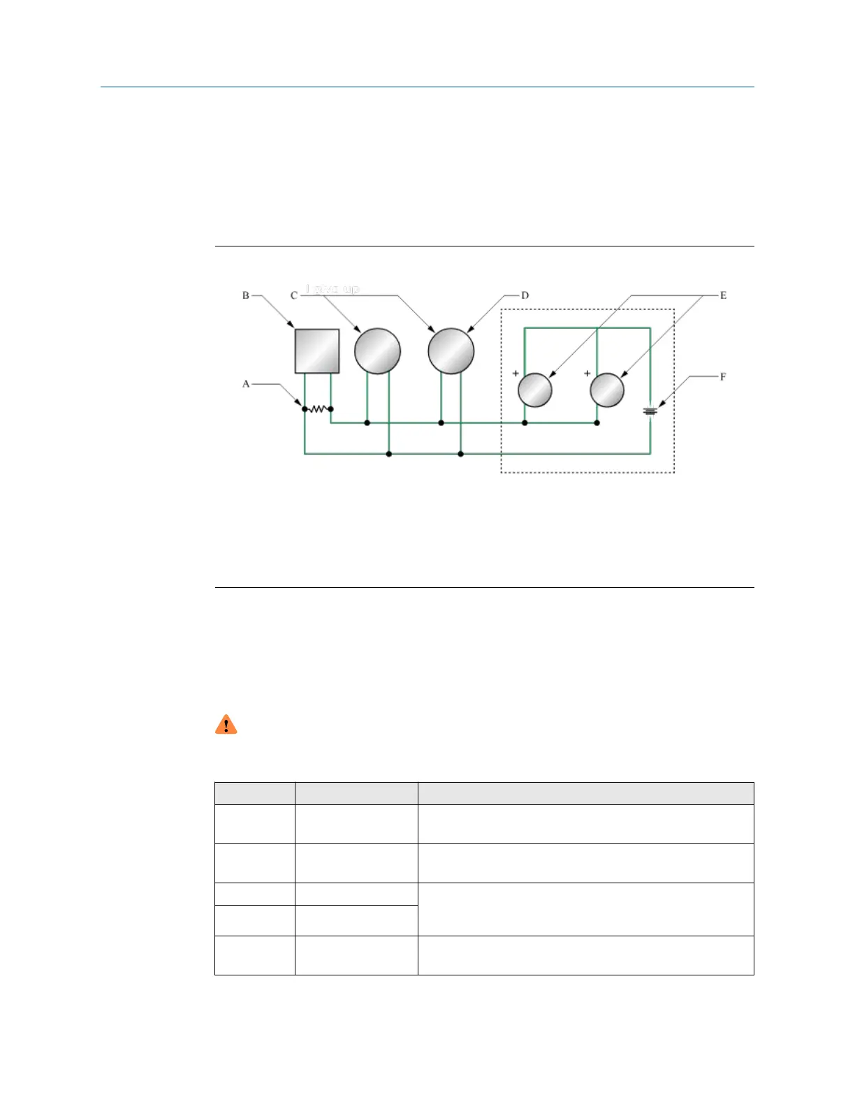
See the Figure 3-10 for information on wiring a mA/HART multidrop installation.
Figure 3-10: mA/HART multidrop wiring
A. 250–600 Ω resistance
B.
HART-compatible host or controller
C.
HART-compatible transmitter (internally powered)
D. Micro Motion 4700 transmitter (internally powered) mA/HART connections
E. SMART FAMILY
™
transmitters
F. 24 VDC loop power supply required for external transmitter
3.5 Wire mA Output 2/Discrete Output/Frequency
Output/ Discrete Input
Use this procedure to wire the externally-powered mA Output 2 and Discrete Input for
Channel B, and Frequency Output and Discrete Output for both Channel A and Channel B.
WARNING
Meter installation and wiring should be performed only by suitably-trained personnel
using the appropriate government and corporate safety standards.
Channel Option Location
A FO2 Wire the frequency output (internally powered)
Wire the frequency output (externally powered)
B FO1 Wire the frequency output (internally powered (Channel B)
Wire the frequency output (externally powered Channel B)
A DO2 Wire the discrete output (internally powered)
Wire the discrete output (externally powered) Channel A or
Channel B
B DO1
B DI Wire the discrete input (internally powered)
Wire the discrete input (externally powered)
Wiring the channels Installation Manual
October2023 00825-0100-5710
28 Micro Motion 4700 CIO Transmitter
 Loading...


