20
Section 3
Rev. 06/15
Safety, Installation, Operations & Service Manual
DOPSM2080X012
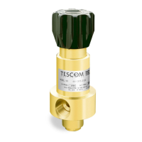
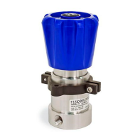
The following steps outline the disassembly of the VA, VG and VT series valves for main-
tenance and repair. For field repairs and maintenance, it is recommended to use the valve
modules for repair. Module numbers are located on the datasheets or call TESCOM for the
module number.
An Assembly Drawing and Bill of Material for the valve will be needed to complete mainte-
nance procedures. The Assembly Drawing and Bill of Material are separate from this manu-
al and available by contacting TESCOM (see pg. 39 for TESCOM contact information).
Special repair tools are available for field servicing valve modules (P/N 64084 for VA mod-
ule and JT103871 for VG module):
1. Clamp the valve body in a vise.
2. Remove the upper portion of the valve bonnet. The actuation side.
3. For the VT valve, also remove the lower bonnet.
NOTE: Upper portion of the valve may also include stem, seals and o-rings. Review correct draw-
ing to ensure that all parts have been disassembled.
Care must be used to not damage sealing components.
3.7.5 Reassembly
The valve is reassembled in the reverse order of disassembly, observing the following pre-
cautions. Please reference Bill of Materials and Assembly Drawings for the correct location
of the replacement parts and correct torque specifications.
1. Inspect all parts and replace those worn or damaged with TESCOM replacement parts.
2. All parts should be cleaned to the cleanliness level required for safe operation with the
media and system the valve will be used in. All parts in the flow stream must be free of
particles which could prevent proper seating on the valve stem.
3. Apply a thin uniform coating of fluorocarbon grease to the following parts: The bonnet
threads and all o-rings.
NOTE: Do NOT apply any type of grease to the inlet and outlet connections.
4. Place the valve body into a vise ad re-torque the bonnet of specifications. See Assembly
Drawing.
After valve has been reassembled, it must be connected to a pressure source with a
media compatible with the use the valve and pressurized to check for internal and
external leakage and operation characteristics.

 Loading...


