5 – 20
Section 5 • Maintenance/Service
VSS/VSR/VSM/VSH/VSSH Compressor • Installation, Operation and Service Manual • Emerson • 35391S
Important Notes
1. Backlash cannot be checked if:
• The gaterotor is damaged in any way.
• The clearance between the gaterotor and the
shelf is too tight.
2. Make sure you check the backlash, not the oat:
• The backlash is the clearance between the
gaterotor teeth width and the rotor groove.
• The oat is the amount of play between the
gaterotor bushing and the damper pins.
Additional Inspections
In addition, visually inspect the main rotor and gatero-
tors for signs of abnormal wear due to dirt or other
contaminants.
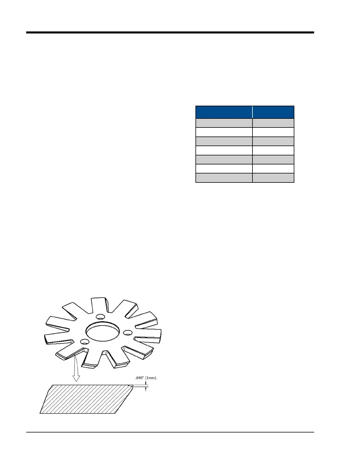
If some chipping is present on the edges of the gatero-
tor, this will not inuence the compressor performance.
If chipping is more than what´s shown on Figure 5-20,
take pictures and contact Vilter Service Department.
Post Inspection
After all the inspections are complete, the gaterotor cov-
er, suction tee, coupling center member and coupling
guard can be reinstalled and the unit can be evacuated
and leak checked before starting.
Figure 5-20. Chipped Edge of Gaterotor
Gaterotor Assembly Replacement
(All Compressors Except VSM 301-701
and VSM 97-127 Compressors)
Table 5-7 lists the gaterotor tool sets needed to remove
and install gaterotor assemblies.
Table 5-7. Gaterotor Tool Kits
Model Tool Set VPN
VSM 97- VSM 127 N/A
VSM 71-VSM 401 N/A
VSM 501-701 A25205B
VSS/VSSH 291-601 A25205B
VSS/VSH 751-1301 A25205C
VSS 1551-2101 A25205E
VSS 2401-3001 A25205F
Removal
1. Remove center member, see appropriate Drive
Coupling Replacement procedure.
NOTE
All parts must be kept with their appropriate side
and not mixed when the compressor is reassembled.
2. Remove two upper bolts from side cover
3. Install guide studs in holes.
NOTE
There will be some oil drainage when the cover is
removed.
4. Remove remaining bolts and side cover.
5. Turn main rotor so a driving edge of any one of the
main rotor grooves is even with the back of the
gaterotor support.
NOTE
The gaterotor stabilizer is designed to hold the
gaterotor support in place and prevent damage
to the gaterotor blade as the thrust bearings and
housing is being removed.
6. Insert gaterotor stabilizer. The side rails are not re-
quired on VSS 451 thru 601. For the VSS 751 thru
901 and VSS 1051 thru 1301 compressors, use the
side rails and assemble to the gaterotor stabilizer as

 Loading...


