1. Alten Tonarm einschließlich Sockel entfernen.
2. Tonarm-Anschlagstift (rechts neben dem Sockel) und
Stützbolzen (unter dem Gegengewicht) entfernen.
3. Auflagebank der Hebe/Senk-Vorrichtung entfernen.Von
der Chassis-Uriterseite (hinten) Hebe/Senk-Mechanik
betätigen:
a) Benzingscheibe von der Achse der Auflagebank ab-
ziehen (wird nicht mehr benötigt).
b) Beide Schrauben am schwarzen Bügel soweit lösen,
bis sich Auflagebank um 360o verdrehen läßt.
c) Auflagebank nach oben abziehen.
ACHTUNG! Feder beachten.
d) Neue, kürzere Auflagebank mit geänderter Position
des Magneten in entsprechend umgekehrter Reihen-
folge montieren.
e) Justierung der Höhe (kann erst nach der Montage
des Tonarmes erfolgen:
Durch Verschieben des schwarzen Bügels auf der
Achse der Auflagebank kann die Höhe dieser ein-
gestellt werden. Bei abgesenktem Tonarm (mit ein-
gesetzterTondose) soll die Abtastspitze sich in Höhe
der Filzauflage des Hilfsplattentellers befinden.
4. Neuen Tonarm-Sockel (Flansch) mit 3 Linsenkopf-Senk-
schrauben und den 3 schwarzen Reduzierscheiben so
auf dem Chassis montieren, daß die beiden Inbus-
schrauben von rechts zugänglich sind.
5. Anschlußleitung an Buchsenleiste für Entzerrerverstär-
ker anlöten (siehe Schaltbild).
6. Tonarm in den Flansch stecken:
Lagerhülse des Tonarms so ausrichten, daß bei nach
innen geschwenktem Tonarm sein Anschlag vor der
Plattentellermitte liegt, d. h. bei eingesetzter Tondose
der Abstand zwischen Tondosengehäuse und Mittel-
zapfen ca. 10 mm beträgt. (VORSICHT: Abtastspitze
der Tondose!)
Danach kann der Tonarm tiefer in den Flansch gesteckt
und die Höhe so justiert werden, daß der Mittelpunkt
des Tonarmlagers 40 mm über der Chassis-Oberfläche
liegt. Mit dem beiliegenden Alublech als Höhenlehre
kann diese Position leicht überprüft werden, so daß
1. Remove old pick-up arm together with socket.
2. Remove pick-up arm stop pin (on the right of the
socket) and the support bolt (underneath the counter-
weight).
3. Remove the support for the pick-up arm lowering dev-
ice. Operate the raising and lowering mechanism from
the underneath side of the chassis (behind):
a) Withdraw surclip from the shaft on the support
(no longer required).
b) Slightly loosen both screws on the black bracket.
c) Withdraw the support plate upwards.
CAUTION! Watch the spring.
d) Fit the new shorter support with different magnet
position in the appropriate inverse order.
e) Height adjustment (can only be carried out after
the pick-up arm has been fitted):
By displacing the black bracket on the shaft of the
support the height of the latter can be adjusted.
When the pick-up arm is lowered (with the head
fitted) the stylus shou!d be in the same plane as
the felt mat on the auxiliary turntable.
4. Fit the new pick-up arm socket (flange) on the chassis
in such a way that the two allen srews are accessible
from the right.
5. Solder the connecting cable to the socket strip for the
equalizer-amplifier (see circuit diagram).
6. Fit pick-up arm into the flange:
Adjust the outer bearing of the pick-up arm so that
with the pick-up arm turned fully inwards, the distance
between the pick-up head and the center pin of the
turntable will be about 10 mm (!/2 inch). (CAUTION:
Avoid damaging the stylus.)
The pick-up arm can now be pressed deeper into
the flange and the height can be adjusted in such a
way that the center of the pick-up arm bearing will
lie 40 mm (1-9/16 inch) above the top of the chassis.
The aluminium height gauge which is supplied may
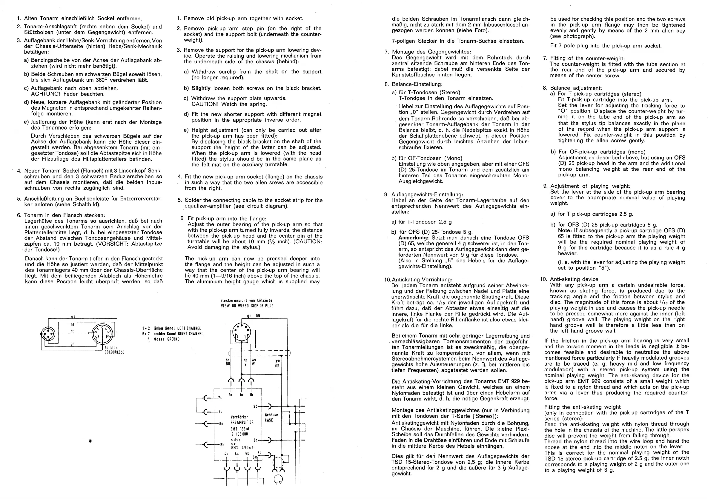
Steckeransichl vün Lotseite
VIEW [)N WlREü SlüE üF PLUG
WS
larbfös
CüLüURLESS
oder 3a-4- 1 ii
i EMT 153St
i Ö ä U
r
1- 2 linker Kanal LEFT CHANNEL
6- 7 rechter Künal RIGHT CHANNEL
k Nasse GRÜlIN[)
gn GN
die beiden Schrauben im Tonarmflansch dann gleich-
mäßig, nicht zu stark mit dem 2-mm-1nbussch1üsse1 an-
gezogen werden können (siehe Foto).
7-po1igen Stecker in die Tonarm-Buchse einsetzen.
7. Montage des Gegengewichtes:
Das Gegengewicht wird mit dem Rohrstück durch
zentral sitzende Schraube am hinteren Ende des Ton-
arms befestigt; dabei muß die versenkte Seite der
Kunststoffbuchse hinten liegen.
8. Balance-Einstellung:
a) für T-Tondosen (Stereo)
T-Tondose in den Tonarm einsetzen.
Hebel zur Einstellung des Auflagegewichts auf Posi-
tion ii0ti stellen. Gegengewicht durch Verdrehen auf
dem Tonarm-Rohrende so verschieben, daß bei ab-
gesenkter Tonarm-Auflagebank der Tonarm in der
Balance bleibt, d. h. die Nadelspitze exakt in Höhe
der Schallplattenebene schwebt. In dieser Position
Gegengewicht durch leichtes Anziehen der Inbus-
schraube fixieren.
b) für OF-Tondosen (Mono)
Einstellung wie oben angegeben, aber mit einer OFS
(D) 25-Tondose im Tonarm und dem zusätzlich am
hinteren Teil des Tonarms eingeschraubten Mono-
Ausgleichgewicht.
9. Auflagegewichts-EinstelIung:
Hebel an der Seite der Tonarm-Lagerhaube auf den
entsprechenden Nennwert des Auflagegeyvichts ein-
stellen:
a) für T-Tondosen 2,5 g
b) für OFS (D) 25-Tondose 5 g.
Anmerkung: Setzt man danach eine Tondose OFS
(D) 65, welche genere114 g schwerer ist, in den Ton-
arm, so entspricht das Auflagegewicht dann dem ge-
forderten Nennwert von 9 g für diese Tondose.
(Also in Stellung ,,5" des Hebels für die Auflage-
gewichts-Einstellung).
10. Antiskating-Vorrichtung:
Bei jedem Tonarm entsteht aufgrund seiner Abwinke-
lung und der Reibung zwischen Nadel und Platte eine
unerwünschte Kraft, die sogenannte Skatingkraft. Diese
Kraft beträgt ca. I/io der jeweiligen Auflagekraft und
führt dazu, daß der Abtaster etwas einseitig auf die
innere, linke Flanke der Rille gedrückt wird. Die Auf-
lagekraft für die rechte Rillenflanke ist also etwas klei-
ner als die für die linke.
Bei einem Tonarm mit sehr geringer Lagerreibung und
vernachlässigbaren Torsionsmomenten der zugeführ-
ten Tonarmleitungen ist es zweckmäßig, die obenge-
nannte Kraft zu kompensieren, vor allem, wenn mit
Stereoabnehmersystemen beim Nennwert des Auflage-
gewichts hohe Aussteuerungen (z. B. bei mittleren bis
tiefen Frequenzen) abgetastet werden sollen.
Die Antiskating-Vorrichtung des Tonarms EMT 929 be-
steht aus einem kleinen Gewicht, welches an einem
Nylonfaden befestigt ist und über einen Hebelarm auf
den Tonarm wirkt, d. h. die nötige Gegenkraft erzeugt.
Montage des Antiskatinggewichtes (nur in Verbindung
mit den Tondosen der T-Serie [Stereo]):
Antiskatinggewicht mit Nylonfaden durch die Bohrung,
im Chassis der Maschine, führen. Die kleine Plexi-
Scheibe soll das Durchfallen des Gewichts verhindern.
Faden in die Drahtöse einführen und Ende mit Schlaufe
in die mittlere Kerbe des Hebels einhängen.
Dies gilt für den Nennwert des Auflagegewichts der
TSD 15-Stereo-Tondose von 2,5 g; die inriere Kerbe
entsprechend für 2 g und die äußere für 3 g Auflage-
gewicht.
be used for checking this position and the two screws
in the pick-up arm flange may then be tightened
evenly and gently by means of the 2 mm allen key
(see phföograph).
Fit 7 pole plug into the pick-up arm socket.
7. Fitting of the counter-weight:
The counter-weight is fitted with the tube section at
the rear end of the pick-up arm and secured by
means of the center screw.
8. Balance adjustment:
a) For T-pick-up cartridges (stereo)
Fit T-pick-up cartridge into the pick-up arm.
Set the lever for adjusting the tracking force to
"O" position. Displace the counter-weight by tur-
ning it on the tube end of the pick-up arm so
that the stylus tip balances exactly in the plane
of the record when the pick-up arm support is
lowered. Fix counter-weight in this position by
tightening the allen screw gently.
b) For OF-pick-up cartridges (mono)
Adjustment as described above, but using an OFS
(D) 25 pick-up head in the arm and the additional
mono balancing weight at the rear end of the
pick-up arm.
9. Adjuätment of playing weight:
Set the lever at the side of the pick-up arm bearing
cover to the appropriate nominal value of playing
weight:
a) for T pick-up cartridges 2.5 g.
b) for OFS (D) 25 pick-up cartridges 5 g.
Note: If subsequently a pick-up cartridge OFS (D)
65 is fitted to the pick-up arm the playing weight
will be the required nominal playing weight of
9 g for this cartridge because it is as a rule 4 g
heavier.
(i. e. with the lever for adjusting the playing weight
set to position "5").
10. Anti-skating device
With any pick-up arm a certain undesirable force,
known as skating force, is produced due to the
tracking angle and the friction between stylus and
disc. The magnitude of this force is about 1/io of the
playing weight in use and causes the pick-up needle
to be pressed somewhat more against the inner (left
hand) groove wall. The playing weight on the right
hand groove wall is therefore a little less than on
the left hand groove wall.
If the friction in the pick-up arm bearing is very small
and the torsion moment in the leads is negligible it be-
comes feasible and desira.ble to neutralize the above
mentioned force particularly if heavily modulated grooves
are to be traced (e. g. heavy mid and low frequency
modulation) with a stereo pick-up system using the
nominal playing weight. The anti-skating device for the
pick-up arm EMT 929 consists of a small weight which
is fixed to a nylon thread and which acts on the pick-up
arms via a lever thus producing the required counter-
force.
Fitting the anti-skating weight
(only in connection with the pick-up cartridges of the T
series (stereo):
Feed the anti-skating weight with nylon thread through
the hole in the chassis of the machine. The little perspex
disc will prevent the weight from falling through.
Thread the nylon thread into the wire loop and hand the
noose at the end into the middle notch on the lever.
This is correct for the nominal playing weight of the
TSD 15 stereo pick-up cartridge of 2.5 g; the inner notch
corresponds to a playing weight of 2 g and the outer one
to a playing weight of 3 g.
 Loading...