Wire the IQ Gateway Metered for Power and Metering
For this step, refer to the Wiring Instruction Sheet for your region.
Energize the IQ Gateway Metered
A ) Close the terminal block door, and secure it with the screw.
B ) Turn on the circuit feeding the IQ Gateway Metered.
C ) All four LEDs ash red during boot up (approximately 2 minutes).
When boot up is complete, the Device Communications LED
lights solid red, indicating that devices are not yet detected.
Launch Enphase Installer App and start System acti-
vation
A ) Launch Enphase Installer App. To create an activation for a new sys-
tem, tap the plus button on the bottom right corner of the screen.
B ) Tap System Details to enter the required information.
C ) Complete the system activation in the Enphase Installer App by lling
in the details.
The “System created successfully” message will display at the bottom
of your screen, and system details will now appear as complete.
Adding Devices and Array to the system
This step is used to enter unique serial numbers of all devices present
on-site. It is recommended that you enter the serial number by scanning
the barcode/QR code.
A ) Tap “Devices and Array” in the home page.
B ) Add the total number of devices to be installed in your system.
C ) Scan device serial numbers through bar code or QR code in respec-
tive device sections
In addition to using your device’s camera to scan serial numbers,
you can enter the serial numbers manually. Manual entry should be
used only when you are not able to scan bar code or QR code of any
device..
D ) After scanning Microinverters, you can use Array Builder to assign
your scanned microinverters to an array or build an array manually.
This step can be completed post commissioning as well.
Setting the tariff details (Optional)
This step is used to enter the electricity rate structure of utility.
A ) Tap “Tariff & Storage Conguration” in the home page.
B ) Subsequently tap on the “Tariff Editor” to enter the electricity import or
export rate. Please ensure that the device is connected to Internet to
complete this step.
IQ Gateway Connectivity
This step is used to establish/monitor IQ Gateway connectivity to
Enphase cloud and to Enphase Installer App. You can also update IQ
Gateway in this step if its needed for successful commissioning.
A ) Tap on the “IQ Gateway Connectivity” in the installer home page.
B ) If the “IQ Gateway” and the “Enphase Installer App” (or the phone
icon) are not connected, please follow the following steps:
- On the IQ Gateway, press the AP mode button (rst button from left)
for about one second. The LED will light solid green.
- Go to your phone’s settings and connect to IQ Gateway’s Wi-Fi
network.
- Return to the Enphase Installer App “IQ Gateway Connectivity” page
and connect.
C ) If the “IQ Gateway” and “Enphase cloud (or the cloud icon)” are not
connected, please follow the following steps:
- The IQ Gateway can connect to the Enphase cloud through either
Wi-Fi, Ethernet, or Cellular.
- If Wi-Fi is selected, input the username and password for the
home/oce Wi-Fi.
- If connecting using Ethernet, simply plug the cable into the IQ
Gateway.
Provisioning the devices
To provision your devices, the Enphase Installer App should be connect-
ed to IQ Gateway via AP mode, as described in IQ the Gateway Connec-
tivity section.
A ) If a green checkmark displays between the IQ Gateway and Enphase
Installer App, tap “START PROVISIONING DEVICES”. The “Provision-
ing Devices” screen displays the steps executed by the Enphase
Installer App. The Enphase Installer App veries and updates the grid
prole in IQ Gateway and provisions all the connected devices.
B ) When provisioning is complete, tap “DONE”.
Verify Meter Conguration
The production meter can be congured as per the following steps:
A ) Tap on the “Meter Conguration” to start conguring the consump-
tion and production meter.
B ) Subsequently, tap on “Production Meter” to start conguring produc-
tion meters. A pop-up notication appears asking to follow the meter
wizard to verify your CT conguration. Select “Yes” to proceed.
C ) Tap “Enable production meter” to nish conguration of the produc-
tion meter.
The consumption meter can be congured as per the following steps:
A ) Tap on “Meter Conguration” to start conguring consumption and
production meter.
B ) Subsequently, tap on the “Consumption Meter” to start conguring
production meters. A pop-up notication appears asking to follow the
meter wizard to verify your CT conguration. Select “Yes” to proceed.
C ) Tap “Enable consumption meter” to nish conguration of the con-
sumption meter.
Send Summary Report and complete Homeowner
Walkthrough
This step is used to enter unique serial numbers of all devices present
on-site. It is recommended that you enter the serial number by scanning
the barcode/QR code.
A ) Tap “Summary” in the Enphase Installer App home page. The system
report is displayed on the screen, which consists of a list of devices,
their serial numbers, their last reports, and information about the grid
prole applied to the devices.
B ) Tap “SHARE” in the right top corner to share the report as needed.
C ) Open the Homeowner Walkthrough and discuss all listed points with
the homeowner. You can also show the videos embedded in the links
to the homeowner for a better experience.
INSTALLATION
Choose a location for the IQ Gateway Metered
A ) Install the IQ Gateway Metered near the switchboard and consider
the length of the CT leads (4 meters) when choosing the location. If
you need to extend the leads (up to 200 meters), refer to the Enphase
IQ Gateway Metered Installation and Operation Manual at: https://en-
phase.com/contact/support
B ) Install the IQ Gateway Metered in a protected dry space. If out-
doors, install the IQ Gateway Metered in an IP54-rated, or better,
enclosure with conduit attachment. Use an appropriately rated
enclosure if hard wiring the IQ Gateway Metered indoors.
NOTE: Metallic enclosures may impair Wi-Fi signal strength.
C ) Mount the IQ Gateway Metered horizontally using the included DIN
rail.
6
5
4
8
7
1
2
3
9
10
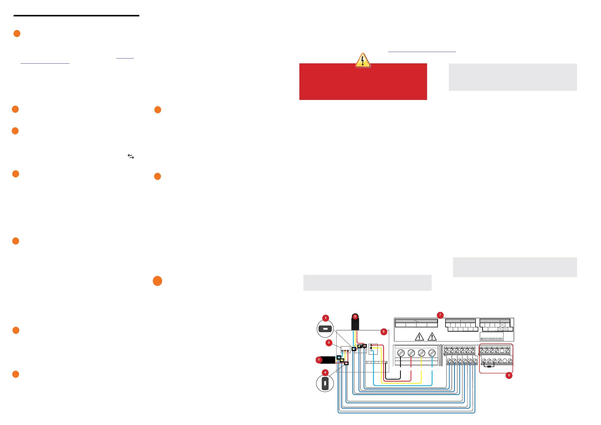
WIRING INSTRUCTION SHEET FOR INDIA
The IQ Gateway Metered uses terminal blocks for power and metering connections. Wire these terminal blocks as described in the following.
You will need to install one split-core CT per monitored phase for production metering and one split-core CT per monitored phase for consumption metering.
Use a protected route in conduit (raceway) for the CT wires to the IQ Gateway Metered. If you need to extend the leads (up to 200 meters), refer to the Enphase IQ Gate-
way Metered Installation and Operation Manual at: https://enphase.com/contact/support.
DANGER! Risk of electric shock. Always de-energise circuits
before wiring for power and CTs.
DANGER! Risk of electrocution! Do not install CTs when current
is owing in the sensed circuit. Always install CT wires in the
terminal blocks before energising the sensed circuit.
A) Before running the CT wires through conduit, use coloured tape to
mark each of the CTs and the free ends of its wires, marking each
with a different colour. You can run multiple CT wires through a
single conduit.
B ) Wire the IQ Gateway Metered for power
•
Depending on the number of phases you will wire, use a one-, two-,
or three-pole (20 A maximum) circuit breaker for the supply wiring.
•
Make sure supply wiring is 2.5 mm
2
copper rated at 75ºC or better.
•
Locate the screw on the terminal block door, and loosen it with a
screwdriver to unlock the door and ip it open.
•
Connect Line 1 to L1, Line 2 to L2, Line 3 to L3, and Neutral to N, as
required.
•
Tighten all connections to 0.56 N m.
C ) Install the Production CTs on phases as required:
•
Locate the arrow on the CT label.
•
To monitor production on Line 1:
-
Connect the white wire to the “I1•” terminal and the blue wire to
the “I1” terminal.
-
Clamp the CT on active Line 1 of the solar production circuit with
the arrow pointing toward the load (away from the solar array).
•
To monitor production on Line 2:
-
Connect the white wire to the “I2•” terminal and the blue wire to
the “I2” terminal.
-
Clamp the CT on active Line 2 of the solar production circuit with
the arrow pointing towards the load (away from the solar array).
•
To monitor production on Line 3:
-
Connect the white wire to the “I3•” terminal and the blue wire to
the “I3” terminal.
-
Clamp the CT on active Line 3 of the solar production circuit with
the arrow pointing towards the load (away from the solar array).
•
Tighten all connections to 0.56 N m
D ) Install the Consumption CTs on phases as required:
•
Locate the arrow on the CT label.
•
Make sure that the AC mains wire(s) are de-energised until you
have secured the CT wires in the terminal blocks.
Note: Only run active conductors of the same phase through
each CT. Each CT can monitor multiple active conductors.
•
To monitor consumption on Line 1:
-
For the rst CT, connect the white wire to “I1•” and the blue
wire to “I1”.
-
Clamp the CT on the main supply Line 1 (active). When the
Consumption CT is on Line 1 (active) conductor, the arrow
must point towards the load (away from the grid).
•
To monitor consumption on Line 2:
-
For the second CT, connect the white wire to “I2•” and the
blue wire to “I2”.
-
Clamp the CT on the main supply Line 2 (active). When the
Consumption CT is on Line 2 (active) conductor, the arrow
must point towards the load (away from the grid).
•
To monitor consumption on Line 3:
-
For the third CT, connect the white wire to “I3•” and the blue
wire to “I3”.
-
Clamp the CT on the main supply Line 3 (active). When the
Consumption CT is on Line 3 (active) conductor, the arrow
must point towards the load (away from the grid).
•
Tighten all connections to 0.56 N m.
NOTE: Because of variance in switchboard design and main power
feed, there may not always be enough space to install CTs.
NOTE: It is important to match CT and voltage sense phases. Be
sure to consistently identify all the AC lines at three points: the main
switchboard feed, the Envoy, and the solar production circuit breaker.
Wire colours may not always consistently identify Lines 1, 2 and 3. If in
doubt, use a multimeter to check.
E ) Install DRM support and a central disconnect as required for Aus-
tralia. The multi-phase IQ Gateway Metered gateway supports DRM
(Demand Response Management). The IQ Gateway Metered (ENV-
S-WM-230 ) has a pre-installed 15 kΩ resistor that provides DRED
bypass when DRED is not required.
NOTE: In systems where a central disconnect (contactor) is installed,
you must congure the meters as described in Step 6 before device
discovery can complete.
I1●
I1
I2●
I2
I3●
I3
I1●
I1
I2●
I2
I3●
I3
1 / 5 2 / 6 3 / 7 4 / 8
NO
RefGen
Com / DRM Ø
C
Production Consumption Digital Input Relay
PD, B300
OVC II
CU, 2.5 mm
2
, 75C
MEAS CAT III
OVC III
L1 L2
L3
N
0
1
2
3
4
5
6
7
8
AU/NZ: DRM Port
N
L1
L2 L3
UPTO 250 Vac.
100A 0.5V 45-66Hz
UPTO 250 Vac.
100A 0.5V 45-66Hz
KEY:
1. Production CT
2. Main isolator switch
3. To meter
4. Consumption CT
5. Output from PV system
6. Switchboard
7. IQ Gateway Metered terminal block
8. Not used
 Loading...