How to Use This Guide
UsethisguidetoquicklysetupyourEnterasys
®
SecureStack
™
B‐Seriesswitch.EnterasysNetworksrecommendsthatyourefer
totheEnterasysSecureStackB‐SeriesHardwareInstallationGuide
associatedwithyourswitchforspecificationsandsafety
warnings.
Thelatestdocumentationislocatedat
www.enterasys.com/support/manuals.
Hardware Components
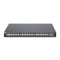
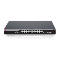
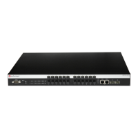
Thefollowingfiguresshowtheseveraltypesoffrontpanelport
andrearpanelconnectionsonyourB‐Seriesswitch.
Figure 1 B2H124-48, B2H124-48P
Figure 2 B3G124-24, B3G124-24P
Figure 3 B3G124-48, B3G124-48P
Figure 4 B-Series Switch Rear
Key
Handling the Switch
Topreventelectrostaticdamage,attachanelectrostaticdischarge
(ESD)wriststraptoyourwristbeforehandlingtheswitch.
Unpacking the Switch
Unpacktheswitchasfollows:
1. Removethepackingmaterialprotectingtheswitch.
2. Removethetapesealonthenon‐conductivebagtoremovethe
switch.
1
Switch Status LEDs
2
RJ45 Ports
3
SFP Ports
4
Combo SFP Ports
5
DB9 RS232 Console Port Connector
6
SFP Port Status LEDs
7
RJ45 Port Status LEDs
8
Stack Connection Ports
9
Password Reset Button
10
AC Power Input Connector
11
Redundant Power Supply (RPS) DC Connector
Caution: The switch can be damaged by electrostatic discharge.
3. Performavisualinspectionoftheswitchforanysignsof
physicaldamage.ContactEnterasysNetworksifthereareany
signsofdamage.See“GettingHelp”formoreinformationon
contactingEnterasysNetworks.
Connecting Power to the Switch
Youcanconnecttoasingle,primarysourceofpower,ortotwo
sourcesofpowerforredundancy.
Thefollowingredundantpowersuppliesareavailabletobe
purchasedfromEnterasysNetworks:
•C2RPS‐PSM,a150wattDCpowersupplycapableofproviding
powertoafully‐loadednon‐PoEswitch.
•C2RPS‐POE
(B2H124‐48P,B3G124‐24P,andB3G124‐48Ponly),
500wattDCpowersupplyforPoEswitches.
Topower‐upyourB‐Seriesswitch:
1. Ifyouareconnectingaredundantpowersupply,attachthe
C2RPS‐PSMcable(fornotPoE)orC2RPS‐POEcable(forPoE)
fromyourredundantpowersupplyto
theA2switch’s
redundantpowerconnector.
2. AttachtheACpowercordtotheB‐Seriesswitch’sACpower
receptacle.
3. Plugtheredundantpowersupply(ifapplicable)andthe
B‐SeriesswitchACpowercordintodedicated,groundedAC
outlets.
4. Oncepowerisconnected,verifytheRPSpowerLEDturns
green,andCPU
(system)LEDturnsamberuntiltheB‐Series
switchfinishesitsinitialization.
5. Iftheinitializationprocessissuccessful,theCPULEDturns
green.IftheCPULEDdoesnotturngreen,refertothe
EnterasysSecureStackB‐SeriesHardwareInstallationGuide
associatedwithyourB‐Seriesswitchfortroubleshooting
information.
Completing Switch Setup and Downloading the Latest
Firmware
OnceyouhaveconnectedpowertotheB‐Seriesswitchand
verifiedLEDactivity,youcancompletethesetupprocessas
follows.RefertotheEnterasysSecureStackB‐SeriesHardware
InstallationGuideassociatedwithyourB‐Seriesswitchformore
information.
1. DeterminethelatestB‐Seriesfirmwareversionbyvisitingthe
EnterasysNetworksdownloadsiteat:
http://secure.enterasys.com/services/support/downloads/software
2. Connecttheswitchtothenetwork.
3. Connectamanagementstationtotheconsoleport.
4. Verifythatthenetworkdevicesconnectedtotheswitchports
arepoweredon,andthateachlink/activityLEDison(solid
greenorblinkinggreen).
5. Atthedeviceconnectedtotheconsoleport,performthe
following:
a. Enteradminfor
Username.
b. AtthePasswordprompt,pressENTER(RETURN).
Electrical Hazard: Only qualified personnel should perform
installation procedures.
Note: Enterasys Networks recommends installing any
components before powering on your switch.
Note: To take full advantage of redundancy, each power supply
should be plugged-in to a separate dedicated AC outlet.
c. Atthecommandprompt,determineifthelatestfirmware
imageisloadedontheswitchbyenteringthiscommand:
show version
d.Iftheoutput(underFWVer si o n)displaysanolderversion
numberthanthatdeterminedinStep1,downloadand
activatethenewversionasdirectedonthedownloadwebsite.
(Alternatively,you
canusetheCLIcommandlistedin
Table 1.)
Basic Setup Commands
Table 1listsCLIcommandsthatarerequiredforsettingupthe
B‐Seriesswitchwiththelatestfirmware.Table 2listsadditional
configurationcommandsforyourB‐Seriesswitch.Forthe
completelistofCLIcommands,seetheEnterasysSecureStackC3
ConfigurationGuide.
Table 1 Required CLI Setup Commands
Step Task CLI commands
1 Set a new password
set password [username]
2 Set the switch IP address
set ip address ip-address [mask
ip-mask] [gateway ip-gateway]
3 Download, activate, and
verify new firmware on the
switch using TFTP copy
Note: You can reboot the
system immediately with the
set boot system command,
or reboot later with the reset
command.
copy
tftp://tftp_server_ip_address/
filename system:image
set boot system filename
show version
Table 2 Optional CLI Setup Commands
Task CLI commands
Save the active configuration
save config
Enable or disable SSH
set ssh enable | disable
Enable or disable Telnet
set telnet {enable | disable}
[inbound | outbound | all]
Enable or disable HTTP
management (WebView)
set webview {enable | disable}
Enable or disable SNMP port link
traps
set port trap port-string
{enable | disable}
Set the per port broadcast limit
set port broadcast port-string
threshold-value
Configure a VLAN
set vlan create vlan-id
set port vlan port-string
vlan-id modify-egress
Set a Syslog server IP and severity
set logging server index ip-addr
ip-addr severity severity state
enable
Configure and enable a RADIUS
server
set radius server index ip-addr
port [secret-value]{realm
{management-access | any |
network-access}
set radius enable
Specifications
Foracompletelistofspecifications,seetheEnterasysSecureStack
B‐SeriesHardwareInstallationGuideassociatedwithyourB‐Series
switch.
Interfaces
B2H124‐48andB2H124‐48P
•FourSFPportsthatsupport1000BASE‐LX,1000BASE‐SX,or
1000BASE‐Tconnections
•Forty‐eight10BASE‐T/100BASE‐TXRJ45ports
B3G124‐24andB3G124‐24P
•Four
comboSFPportsthatsupport1000BASE‐LX,
1000BASE‐SX,or1000BASE‐Tconnections
•Twenty‐four10BASE‐T/100BASE‐TX/1000BASE‐TRJ45ports
B3G124‐48andB3G124‐48P
•FourcomboSFPportsthatsupport1000BASE‐LX,
1000BASE‐SX,or1000BASE‐Tconnections
•Forty‐eight10BASE‐T/100BASE‐TX/1000BASE‐TRJ45ports
Switch Dimensions
Size:354.40x441x44.0mm
Power Consumption
InputVoltage:100to240VAC
Temperature and Humidity
Operating:0ºCto50ºC
Storage:‐40ºCto+70ºC
Getting Help
Related Documents
ThelatestB‐Seriesdocumentationislocatedonlineat:
www.enterasys.com/support/manuals
Note: The RJ45 ports on the B2H124-48P, B3G124-24P, and the
B3G124-48P also support 802.af PoE connections.
World Wide Web www.enterasys.com/services/support/
Phone 1-800-872-8440 (toll-free in U.S. and Canada)
or 1-978-684-1000
To find the Enterasys Networks Support toll-free
number in your country:
www.enterasys.com/services/support/contact/
Internet mail support@enterasys.com
To expedite your message, type [Switching] in the
subject field of your message.
Latest image and
release notes
www.enterasys.com/services/support/downloads/
software/


 Loading...