Environnement S.A MP101M Duplication prohibited
SEPTEMBER 2013
2–6
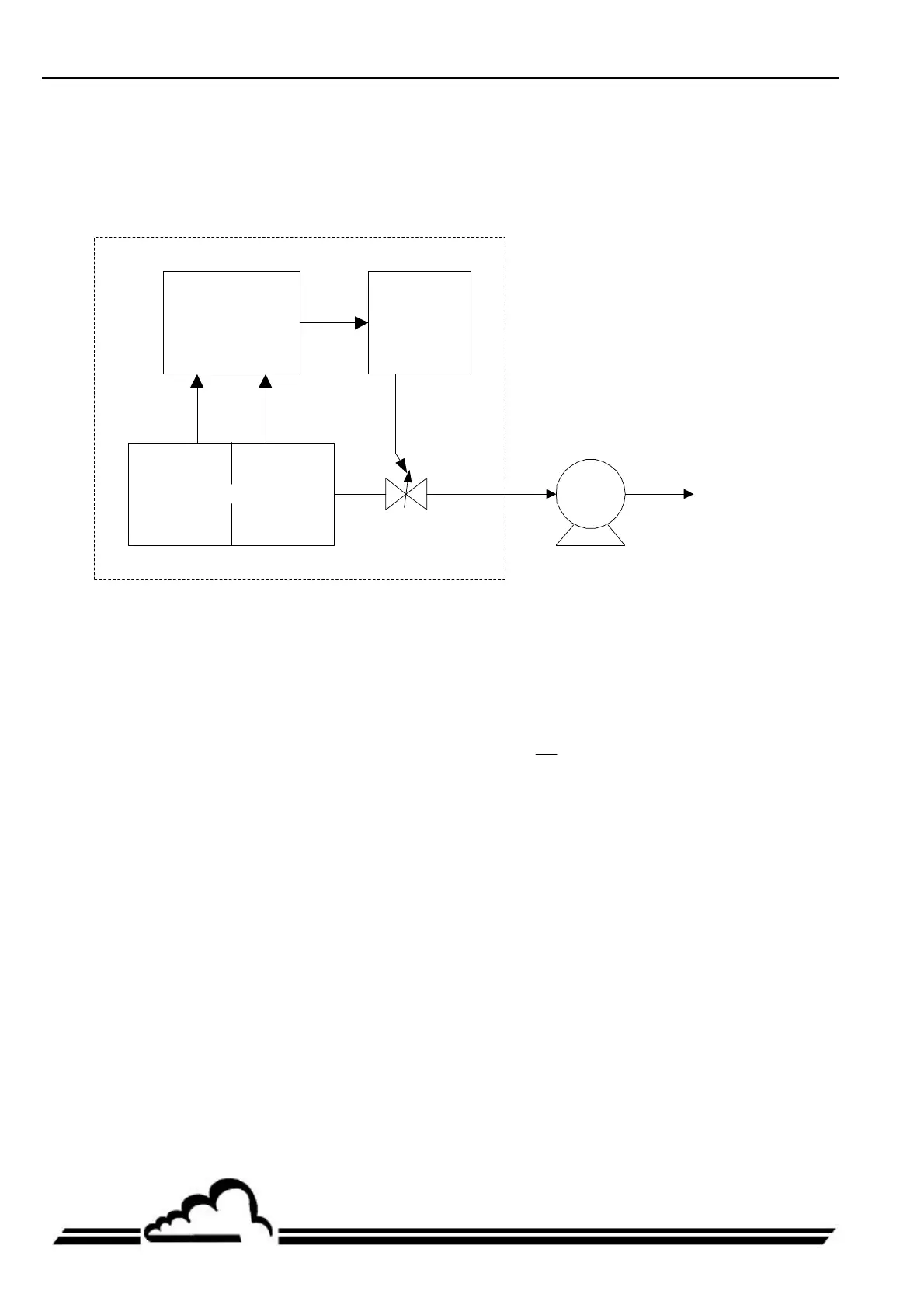
2.2. FLOW REGULATION PRINCIPLE
The sample is taken at a constant volume flow rate with compensation of load loss due to the filter and
progressive depositing of dust.
The flow rate is therefore controlled and maintained at the selected reference value of 1.0 m
3
/h.
Command
and control
Motor
External
pump
P1 P2
MP101M
Fluid flow direction
Figure 2-3 – Flow regulation diagram
P
1
and P
2
designate the absolute static pressures measured on both sides of the diaphragm through
two axial holes perpendicular to the fluid flow direction and located very near the diaphragm.
The diaphragm is machined and arranged to produce a turbulent flow in the immediate vicinity. The
diameters of the conduit and orifice are sized such that,
P
P
2
1
> 0.9 in most cases, whereby the flow
can be considered as incompressible, minimizing load loss effects.
 Loading...