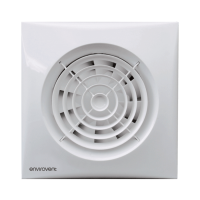
CLASSIC – 100 S
This model uses the following wiring diagrams:
Fig.7. Fan operating through a light switch.
Fig.8. Fan operating through an independent switch.
CLASSIC - 100 X Models (XP, XHP, XT)
Models fitted with thermo-electric automatic shutter.
WARNING: The opening of the shutter is facilitated by means of a thermal system
that requires a few seconds to open completely.
CLASSIC - 100 XP (Fig. 9)
Single speed fan, fitted with thermo-electric shutter and integral pullcord.
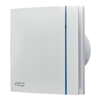
CLASSIC - 100 H Models (XHP, XHT, HP)
Provided with an integral humidity sensor, which can be adjusted from 60-90% RH by
the rotary switch on the front of the fan without removing the grille. The controller is
facto ry s et to approx. 72% RH.
To lower the RH, turn the adjuster towards the minus sign. The fan will operate
more frequently, as the controller will be more sensitive.
To increase the RH, turn the adjuster towards the plus sign. The fan will operate
less frequently, as the controller will be less sensitive.
CLASSIC-100 HP (Fig. 10)
Automatic operation with pull cord switch enabling override of the fan when the relative
humidity level in the room is lower th an the set % RH value.
CLASSIC –100 XHP (Fig. 10)
Fitted with thermo-electric shutter and pull cord switch enabling override of the fan when
the relative humidity level in the room is lower than the set % RH value.
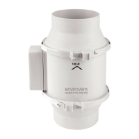
CLASSIC - 100 T Models (T, XT)
The timer enables the fan to continue running for the selected period after the switch has
been turned off. The desired run-on time is selected by means of an adjuster “T” posi-
tioned on the printed c ircuit board (Fig.13).
CLASSIC –100T&XT
Fig.11. Fan operating through a light switch.
Fig.12. Fan operating through an independent switch.
CLASSIC –100 XHT
Fitted with thermo-electric shutter, humidity sensor and timer.
Fig. 14. Fan operating through a light switch
Fig. 15. Fan operating through an independent switch
•
•
•
•
•
•
 Loading...