Page 1 of 5
109-6182 Rev. A
Loose Parts
Note: Use the chart below to verify that all parts have been shipped.
109-6181 Dealer Pack
Part # Description Qty Use
323-6
98-5975
3290-357
Cap Screw, Hex 3/8-16 x 1
Washer, Belleville
Nut, Hex Flange 3/8-16
8
8
8
Installing the Rollover Protection System (Roll Bar)
103-1309 Warranty Registration Form 1 Fill out and return to Exmark
103-2106 Keys 1 Unit ignition
32128-20 Nut, 5/16-18 Whizlock 4 For fastening seat tracks to unit seat frame
1-303335 Tie, Plastic 2 For fastening seat wiring to seat prop rod
109-6178 Literature Pack
Part # Description Qty Use
-----------
-----------
Manual, Operator’s
Manual, Parts
1
1
Read before operating machine.
109-3498 DVD, Exmark Safety Video 1 View before operating machine.
109-6435 Sheet, Emissions Warranty 1
Installing the Rollover Protection
System (Roll Bar)
1. Remove sides and top of crate from the base.
2. Remove roll bar components from the crate.
3. Remove roll bar tubes from sides of crate.
4. Remove the two brackets used to mount the
bottom of the upper roll bar tube to the crate.
5. Remove the 1/2-13 x 3 1/4 capscrews and 1/2-13
hex flange lock nuts from the two brackets at
each end of the upper roll bar tube and retain for
later use (Fig. 1).
6. Remove the (4) 1/4” lag screws holding the wheel
hub brackets to the crate bottom and discard.
7. Raise the rear of the unit approximately 10-12”
and support it with jack stands or equivalent
support.
CAUTION
POTENTIAL HAZARD
♦ Raising the rear of the unit for assembly relying
solely on mechanical or hydraulic jacks could
be dangerous.
WHAT CAN HAPPEN
♦ The mechanical or hydraulic jacks may not be
enough support or may malfunction allowing
the unit to fall, which could cause injury.
HOW TO AVOID THE HAZARD
♦ DO NOT rely solely on mechanical or hydraulic
jacks for support. Use adequate jack stands or
equivalent support.
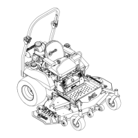
8. Locate the left and right lower roll bar tubes.
9. Align lower roll bar tubes along rear engine frame
(Fig. 2).
10. LOOSELY install lower roll bar hardware (four
3/8-16 x 1 capscrews, four spring disk washers
and four 3/8-16 whizlock nuts) to the tubes on
each side. (Fig. 2).
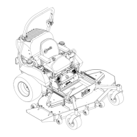
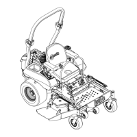
LAZER Z
(AIR COOLED)
SETUP INSTRUCTIONS
FIGURE 1
For Serial Nos. 670,000 and Highe